
Switchgear does four jobs in a distribution system: it carries current along a busbar and out to each feeder, it switches circuits for operation and maintenance, it interrupts faults without destroying itself, and it provides an isolation point that can be proved and earthed before people work on the network. Everything inside a metal-enclosed cabinet exists to serve one of those four functions, and almost every specification argument about switchgear is really an argument about which of them a particular project is prepared to pay for.
The word covers a range of equipment — a ring main unit on a pole, a withdrawable circuit breaker panel in a substation, a metal-clad switchboard in a factory — and the four functions are distributed differently across those forms. A load break switch can do two of them well and one of them not at all. A vacuum circuit breaker does three, and depends on a disconnector for the fourth. Understanding which device provides which function is what makes a single-line diagram readable and a quotation comparable.
What follows takes the four functions in order, shows where each one physically lives in a cabinet, and sets out what to specify so that a function is actually delivered rather than assumed from the words on a datasheet.
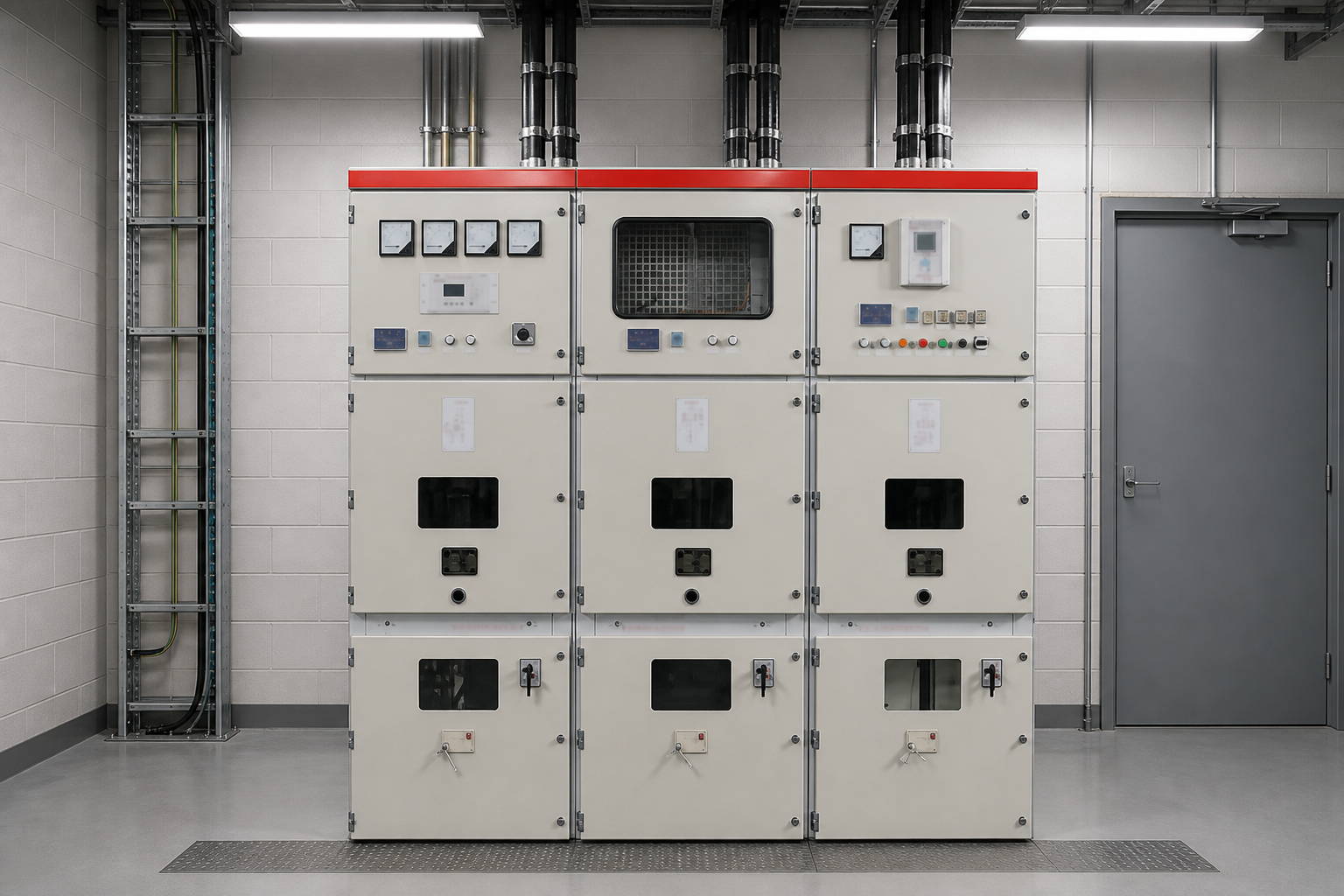
What Does Switchgear Do in a Distribution System?
A distribution network is a set of nodes that must be connected and disconnected without stopping the network, protected without being destroyed, and worked on without being touched while live. Switchgear is the equipment that makes those three things possible at each node. It is not a transformer: it does not change voltage. It is not a meter: it does not measure energy for billing, although it carries the instrument transformers that do. Its contribution is control — of the path, of the current, and of the risk.
The clearest way to see the four functions is to follow a fault. In normal operation the switchgear is a low-resistance path from the incoming busbar to each outgoing cable. When a feeder is to be maintained, the switchgear creates a visible break and an earth. When a fault occurs downstream, the switchgear nearest the fault opens within its rated breaking time, and the rest of the network continues to run. Each of those is a different function performed by a different part of the same cabinet, and each has its own rating.
| Function | Physical provision inside the cabinet | Rating that proves it |
|---|---|---|
| Carry current | Main busbar, branch bars, joints, cable terminals | Rated normal current, temperature rise, short-time withstand |
| Switch load | Load break switch, contactor or circuit breaker mechanism | Rated breaking current for the load type, mechanical endurance |
| Clear faults | Vacuum interrupter, arc control, protection relay | Rated short-circuit breaking current, making current, operating sequence |
| Isolate and earth | Disconnector or draw-out contacts, earthing switch, interlocks | Isolating distance, short-time withstand of the earth switch, interlock logic |
Function One: Carrying Current Without Becoming the Fault
The busbar and its joints are the least dramatic and most consequential part of the cabinet. A busbar has to carry the rated current continuously without exceeding the temperature-rise limit of its insulation and its enclosure, and it has to survive a short-circuit for the time the upstream protection takes to operate. Those are different tests: a joint that runs cool at 630 A can still be the point that fails at 25 kA for one second.
Three details decide whether the rating is real. The first is the joint: bolted joints depend on plating, contact pressure and torque, and a joint assembled without a torque record is an assumption rather than a connection. The second is the support spacing, because the electromagnetic force between bars during a short circuit is proportional to the square of the current and rises as the span between supports increases. The third is ventilation of the busbar compartment, since a bar that runs at its limit in still air has no margin for a room that reaches 45 °C in summer.
This is also the function that degrades invisibly. Contact resistance rises slowly at a joint that was never quite tight, the temperature at that joint rises with it, and the process accelerates until the insulation around it fails. That is why thermal survey of a switchboard is worth more than a yearly visual inspection, and why the rating discussion in the busbar current rating guide is really a discussion about allowable temperature rise.
Function Two: Switching Load Without Drawing an Arc
Opening a circuit that is carrying current produces an arc, and the device has to manage that arc until the current crosses zero and stays there. The three families of device in distribution switchgear handle the arc differently, and the difference is what makes one suitable for a ring main unit and another for a motor feeder.
- Load break switches interrupt normal load current in air, SF6 or vacuum, and are rated for the load currents they will actually see — transformer magnetising current, cable charging current, a feeder at full load. They are not rated to interrupt a short circuit, and a network that relies on them for fault clearance is relying on the upstream breaker.
- Vacuum circuit breakers interrupt both load and fault current, with a vacuum interrupter that quenches the arc at current zero and a mechanism that provides the speed and energy to separate the contacts fast enough. Their advantage is that the same device covers switching and protection, which is why a single breaker panel can replace a switch plus a fuse.
- Contactors and fused contactors are built for frequent operations on loads such as motors and capacitors, where the number of operations rather than the fault level dominates the design life. They depend on the fuse or the upstream breaker for fault clearance.
The specification point that gets missed is the operating duty. A device rated for 10,000 mechanical operations may be rated for far fewer short-circuit interruptions, and a capacitor bank switched daily will consume its endurance in a way a feeder switched twice a year never will. The load break switch guide covers the load types that stress this function most.
Function Three: Clearing a Fault Without Destroying the Cabinet
Fault clearance is the function that separates switchgear from a switch. A short circuit on a feeder produces a current an order of magnitude above normal, and the cabinet has to break it, withstand it while the protection decides, and contain the consequences if the interruption fails.
Four ratings describe that capability, and they are routinely confused in quotations. Rated short-circuit breaking current is what the device can interrupt. Rated short-circuit making current is the peak it can close onto, which is higher because of the asymmetry of the first cycle. Rated short-time withstand current is what the busbar and the earthing system can carry while waiting for the protection to operate. Rated peak withstand current is the electromechanical limit of the bars and supports. A cabinet quoted with a breaking current but no short-time figure has answered only half the question.
The other half is the protection that commands the trip. A breaker with a 25 kA rating and a relay set to 0.5 s clears the same fault as one set to 0.1 s, but the equipment and the people near it live with the difference. Coordination — the study that decides which device trips first and how fast — is what turns a collection of rated devices into a protective system, and it is the part of the package that is hardest to verify from a datasheet.
Internal arc performance belongs here too. Metal-enclosed switchgear is classified by the accessibility and the arc containment it provides, and a cabinet that is merely enclosed is not the same as one tested to contain an arc and vent it away from the operator. Where the room is small or the panel is in a public building, that classification is the difference between a fault and an incident.
Function Four: Isolating and Earthing for Work
The fourth function exists for people rather than for the network. Before work begins, the circuit has to be disconnected from every source, the disconnection has to be visible or provable, and the conductor has to be connected to earth at the point of work. Switchgear provides all three, and the interlocks that make them happen in the right order are as much a part of the function as the blades themselves.
Isolation in a metal-enclosed cabinet is achieved either by a disconnector with a visible break or by draw-out contacts that physically separate when the truck is racked out. The second is only an isolation point if the shutter closes behind the truck and the position indicator is honest; a racked-out breaker with a jammed shutter is not isolated, it merely looks it.
Earthing is performed by a switch rated for the short-circuit current that could flow through it if the circuit is energised in error, which is why an earthing switch has a short-time withstand rating of its own. The interlock that prevents closing the earthing switch while the disconnector is closed, and prevents closing the disconnector while the earth switch is closed, is a mechanical promise that maintenance staff rely on. It is also the promise most often defeated by a bent linkage or a missing padlock during commissioning.
This function is where the four-part division becomes visible as compartments. A withdrawable panel separates the busbar, the breaker, the cable and the low-voltage controls into distinct spaces, so that work in one does not expose another. The metal-enclosed switchgear guide sets out the partition arrangements and what each one buys.
Which Functions Live in Which Compartment?
Once the four functions are named, the internal layout stops being arbitrary. The busbar compartment carries current and must be rated and supported for the fault level. The breaker compartment holds the switching and interrupting device and must vent an arc. The cable compartment is the isolation and earthing point and is where a person's hands go. The low-voltage compartment holds the protection and control that commands the other three.
| Compartment | Functions served | What to check in the design |
|---|---|---|
| Busbar | Carry current | Support spacing, joint treatment, temperature rise at rated current |
| Breaker or switch | Switch load, clear faults | Interrupter rating, operating sequence, mechanical endurance |
| Cable | Isolate, earth, terminate | Earth switch rating, interlock logic, termination space, sealing |
| Low voltage | Command and measure | Relay settings access, CT/VT wiring, test terminals, segregation from power |
Partitioning is what allows a cabinet to be worked on safely while the rest of the board stays live. A single-compartment design can still perform all four functions; it simply performs them with the whole board dead, which for a data centre or a hospital is not a function at all.
What Switchgear Does Not Do
Three exclusions are worth stating because each one is discovered late in projects.
It does not limit fault current. A breaker interrupts what the network delivers; it does not reduce it. Where the fault level exceeds the equipment rating the answer is a reactor, a different network configuration or higher-rated gear, not a larger breaker.
It does not protect people from every arc. Containment is a tested classification with defined boundaries — the accessible sides, the indicators, the vent direction. A cabinet tested for an arc on the front is not thereby safe on the rear, and a room that puts the rear against a corridor has moved the risk rather than removed it.
It does not replace the earthing system of the building. The switchgear earth bar is a connection point, and its performance depends on the room earth it is bonded to, which the earthing and bonding guide treats as a separate design problem.
How Should the Four Functions Be Specified?
A specification that names equipment types invites a comparison of catalogues. A specification that names functions invites a comparison of capability, which is what the buyer actually needs.
- State the load and the duty. Continuous current, the load types to be switched, and how often. A capacitor feeder and a transformer feeder of the same rating are not the same duty.
- State the fault level and the clearing time. Breaking current, short-time withstand and the protection operating time, as three separate numbers.
- State the isolation requirement. Visible break or draw-out, earthing switch rating, and the interlock schedule in words rather than as a reference.
- State the arc classification and the accessible sides. Including where the cabinet will stand and which face is exposed to a walkway.
- State the ambient and altitude. Both derate the equipment, and both are frequently omitted from the enquiry.
Those five lines fit on one page and eliminate most of the ambiguity in a switchgear quotation. They also make the type test report readable: every number in the report answers one of them.
Where Nahu Group Fits
Nahu Group builds the equipment that performs these four functions for 11 kV and 33 kV networks: metal-enclosed and armoured switchgear, ring main units, vacuum circuit breakers, load break switches, isolating and earthing switches, and the instrument transformers and metering boxes that ride on the same cubicles. Because the range covers the devices on both sides of the isolation point, the function schedule can be checked against what each cabinet actually contains.
The useful input from a buyer is the single-line diagram with the fault level and the duty written on it. From that, the distribution cabinet range can be configured by function — which compartment does what — instead of by model number, and the type test evidence can be matched to the ratings the project actually needs.
Switchgear is bought for what it prevents: an outage that spreads, a fault that damages the board, a person who works on a circuit that was not truly isolated. The four functions are the checklist for whether it will.
Frequently Asked Questions About Switchgear Function
What are the four functions of switchgear?
Carrying current along the busbar and out to each feeder, switching load for operation and maintenance, interrupting fault current, and providing a provable isolation point that can be earthed before work begins. Each function is performed by a different part of the cabinet and carries its own rating.
Does switchgear change voltage?
No. Switchgear connects, disconnects and protects circuits at one voltage level. Voltage transformation is the job of the power transformer, which the switchgear protects and isolates but does not replace.
Can a load break switch clear a fault?
No. A load break switch is rated to interrupt normal load current - transformer magnetising current, cable charging current, a feeder at full load - but not short-circuit current. Fault clearance depends on the upstream breaker or a fuse.
What is the difference between a circuit breaker and a disconnector?
A breaker interrupts load and fault current and can be closed onto a fault within its making rating. A disconnector provides a visible isolating gap but must not be operated under load. The two are interlocked so that the disconnector only opens after the breaker has cleared.
Why does switchgear need an earthing switch?
So that the circuit can be connected to earth at the point of work, and so that the earth connection can carry the fault current that would flow if the circuit were energised in error. The earthing switch therefore has its own short-time withstand rating and its own interlock with the disconnector.
Which ratings should be compared in a switchgear quotation?
Four numbers, not one: rated short-circuit breaking current, rated short-circuit making current, rated short-time withstand current and rated peak withstand current. A quotation that gives only a breaking current has answered half the question, because the busbar and the earth path are rated by the other two.
Published November 2, 2026 · Nahu Group (NAHU Electric Technology)