
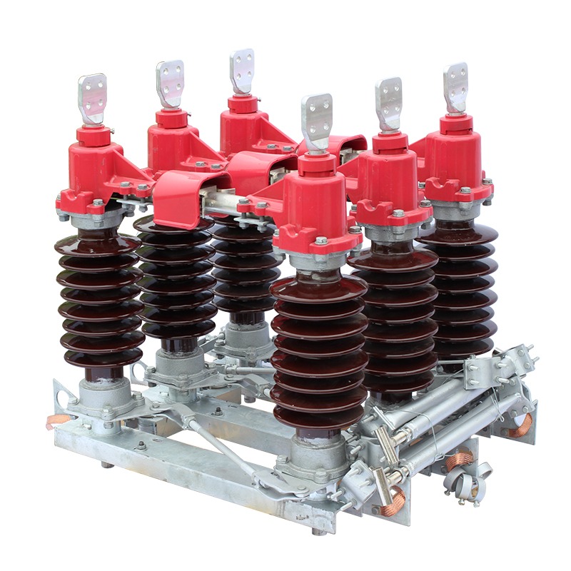
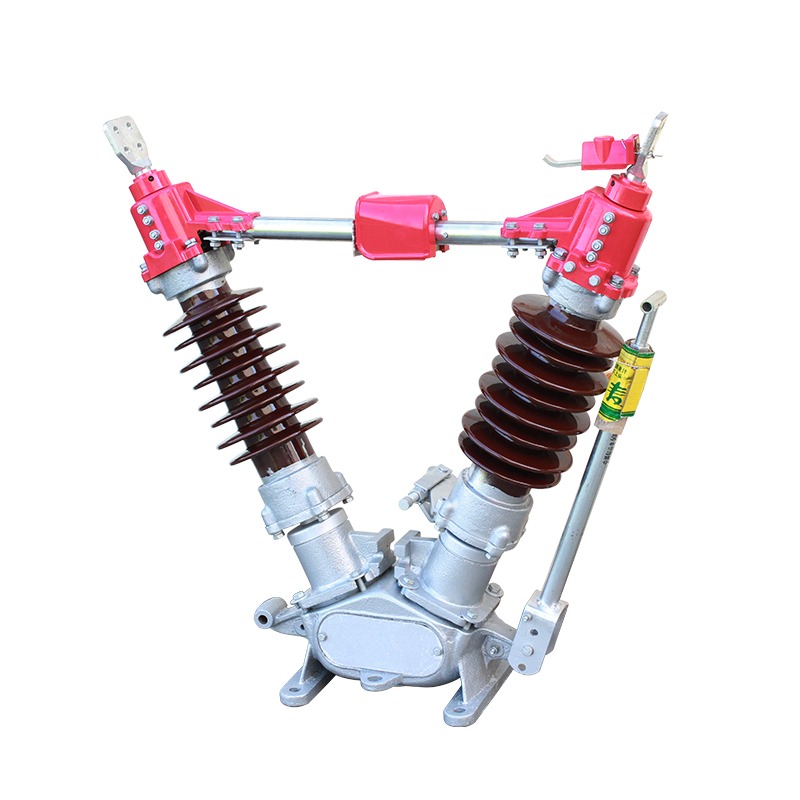
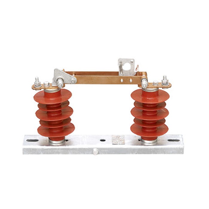
Before anyone works on a high-voltage circuit, they need to be certain it is dead — not just switched off, but visibly, physically separated from the live network. That certainty is the job of the isolating switch, or disconnector. It provides an air gap you can see across, isolating equipment and personnel from energised busbars and lines.
Isolating switches look simple — a blade that swings open — but the engineering behind them is exacting: they must carry full rated current indefinitely, survive short-circuit forces, operate reliably for decades outdoors, and still leave no doubt about their state.
What an Isolating Switch Does
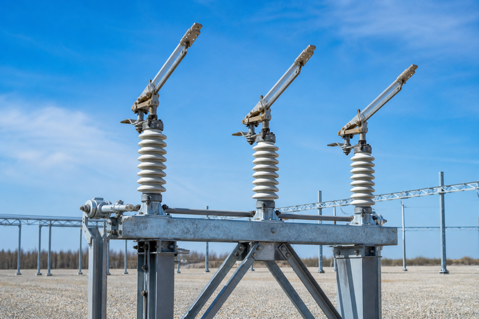
An isolating switch (disconnector) is a mechanical switching device that provides a visible isolation gap in a circuit for safety and maintenance. Its three defining characteristics:
- Visible break — the open position leaves a clearly visible air gap on every phase, so crews can confirm isolation with their own eyes
- No load-breaking duty — a disconnector has no arc-quenching capability and must only be operated when the circuit is de-energised (or with negligible current), never to interrupt load or fault current
- Safety and earthing role — after opening, the isolated section can be earthed via the earthing switch, making the working zone verifiably dead on both fronts
In substations and distribution panels, disconnectors are interlocked with the circuit breaker: the breaker must be open before the disconnector can be operated, preventing any attempt to open or close the disconnector under load. The interlock is mechanical, electrical or both — and it is a mandatory part of a safe switching sequence.
Isolating Switch vs Circuit Breaker vs Load Break Switch
The three devices are often confused because they all sit in the same circuit, so it is worth stating the difference sharply:
- Circuit breaker — interrupts load current AND fault current; used for protection; must operate under load and short-circuit
- Load break switch — interrupts normal load current, but not fault current; used where load switching is routine but protection is provided upstream
- Isolating switch (disconnector) — interrupts nothing; provides a visible, safe isolation gap only, always operated de-energised
In a typical feeder, the disconnector sits on either side of the breaker: source-side disconnector, breaker, line-side disconnector, then the earthing switch on the outgoing side. This lets any section be isolated and earthed while the rest of the busbar stays live.
Indoor Types
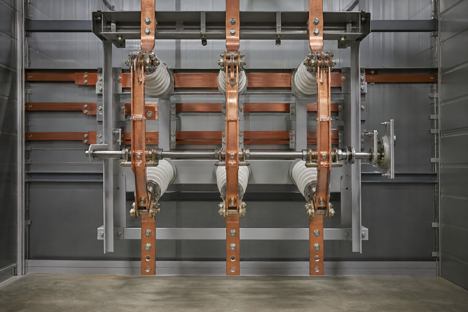
Indoor disconnectors live inside switchgear rooms, ring main units and distribution panels, where space is tight and the environment is protected from the weather. The two workhorse designs are:
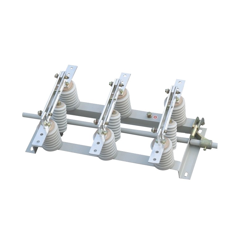
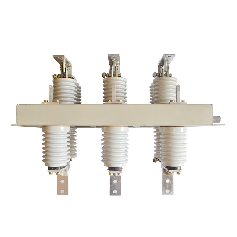
- GN19-12 — the classic three-pole indoor disconnector for 12 kV panels; vertical-opening blades mounted on a common base frame, manually or motor operated, with optional earthing blades
- GN30-12 — the rotary disconnector; the contact rotates in and out of the circuit, giving a compact footprint and a clean visible break inside the cubicle
Indoor units are compact because the panel does the weather protection, and they prioritise reliable operation over creepage distance. They are usually supplied as a three-pole assembly with an operating handle through the panel door, mechanical position indication, and interlocking provisions that stop the door being opened while the switch is closed.
Outdoor Types
Outdoor disconnectors work in substation yards and on poles, where they face rain, ice, pollution and full sun. Long creepage distances, robust bearings and weatherproof drives are the price of admission. The main families:
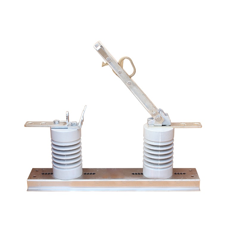
- GW1-12 — pole-mounted outdoor disconnector, simple and rugged for distribution lines
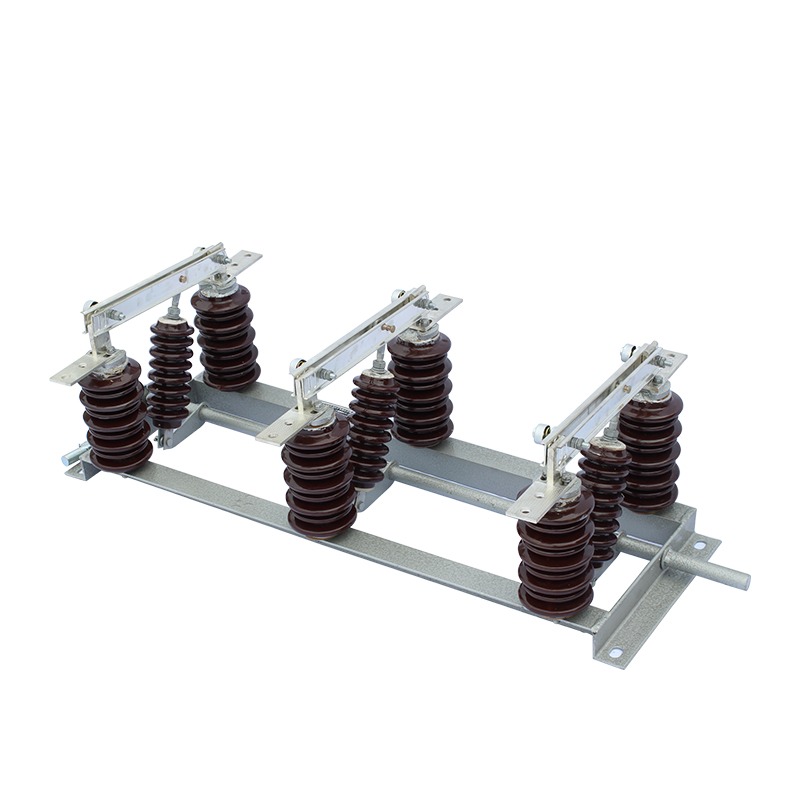
- GW4 — the centre-break design: the blade splits in the middle and both halves swing to open the gap; the most common substation disconnector at 40.5 kV and below
- GW5 — double-break or V-type design with two blades rotating about the insulator tops; excellent for wide conductor spacing
- GW9-12 and GCD-12KV — pole-mounted disconnectors with optional load-break fuses or fused combinations for distribution duty
Operation is by manual handle, or by motor mechanism for remote and automated switching. Outdoor units commonly include auxiliary contacts for position indication to the control system — the control room must know the blade really moved, because the operator cannot see it.
Key Ratings
Disconnector ratings follow IEC 62271-102 and map directly to the network they serve:
- Rated voltage — 12 kV for distribution panels and feeders; 40.5 kV for sub-transmission yards
- Rated current — the continuous current the closed switch must carry without overheating, e.g. 400 A, 630 A, 1250 A, 2000 A
- Short-time withstand current — the fault current the switch must survive closed for 3 s (e.g. 20 kA/3 s or 25 kA/3 s)
- Peak withstand current — the first-cycle peak, typically 2.5× the short-time value, which stresses contacts and structure with electrodynamic force
- Mechanical endurance — the number of operations guaranteed without maintenance (typically 2,000–10,000)
- Operating mechanism — manual, spring-assisted or motor drive, matched to frequency of operation and automation needs
The short-time and peak withstand ratings are the ones that protect lives in a different sense: a disconnector that cannot survive the fault current of its own busbar can blow itself apart — or worse, unload a live conductor — when a short circuit occurs elsewhere in the yard.
How to Choose
Selection is a short, fixed list of questions:
- Location — indoor panel (GN19, GN30) or outdoor yard/pole (GW1, GW4, GW5, GW9, GCD)?
- System voltage — 12 kV class for distribution, 40.5 kV for sub-transmission
- Continuous current — match to feeder load with margin, e.g. 630 A or 1250 A
- Fault duty — short-time and peak withstand current must cover the system's maximum fault level
- Operating requirements — manual, motor, or remote position signalling; frequency of operation
- Accessories — earthing blades, auxiliary contacts, interlocks, and anti-condensation or heater options where relevant
- Standards — specify to IEC 62271-102 so the unit is accepted by the network operator
When in doubt between two sizes, the current and fault ratings should follow the circuit's real duty — not an arbitrarily larger frame. Oversizing costs money and space; undersizing is a safety issue, which is worse.
Operation Safety
The rules of disconnector operation are simple and absolute:
- Operate only when the circuit is de-energised — the breaker must be open and confirmed, with the interlock respected
- Verify the open position visually after operating — the visible gap is the whole point of the device
- Close the earthing switch before touching or working on the isolated section
- Never use a disconnector to break load or fault current — that is the breaker's job
Every failure mode that injures people around disconnectors comes from operating them live: arcing across the gap, damage to the blade, and the violent consequences of opening under load. Interlocks, padlocks and operating procedures exist to make a live operation impossible, and the discipline of verifying by sight completes the safety chain.
Q&A
Question: Can an isolating switch break load current?
Short answer: No. A disconnector has no arc-quenching capability and must only be operated de-energised. Opening it under load creates a violent arc that can destroy the device and endanger personnel.
Question: Why does the isolation gap have to be visible?
Short answer: Because the human eye, not a flag or a signal, is the final confirmation that a circuit is dead. A visible air gap on every phase removes any doubt before earthing and work begins.
Question: What is the difference between indoor and outdoor disconnectors?
Short answer: Indoor units (GN19, GN30) are compact three-pole assemblies for switchgear panels; outdoor units (GW1, GW4, GW5, GW9, GCD) have longer creepage distances, weatherproof bearings and drives, and handle rain, ice and pollution in substation yards and on poles.
Question: How often should disconnectors be maintained?
Short answer: Annually in outdoor yards — clean contacts, lubricate bearings and drives, check the interlock and position indication — plus after any through-fault, when the short-time current stress should be inspected and contact resistance re-verified.
Nahu Group (NAHU Electric) manufactures GN-series indoor disconnectors (GN19-12, GN30-12) and GW-series outdoor isolating switches (GW1, GW4, GW5, GW9 and GCD-12KV) for 12–40.5 kV systems, with earthing blades, motor drives and IEC 62271 compliance. For ratings and configuration support, see our isolating switch range, or contact our engineering team.
Published August 20, 2026 · Nahu Group (NAHU Electric Technology)