
Switchgear earthing is the bonded metallic path that connects every conductive part of an installation — enclosure frames, cable screens, instrument-transformer cases and the earthing switch — back to the site earth. A main earthing bar runs through the switchgear and gives those connections one low-impedance, testable point. Bonding is what makes an enclosure safe to touch during a fault. The electrode system in the ground is what dissipates the fault current once it gets there.
The three parts are usually discussed as one subject, and that is where the mistakes start. A panel can have a perfectly sized earthing bar and still be unsafe, because a door was painted after bonding, or because a cable screen was left floating, or because the earthing switch is bonded to the bar but the bar is not bonded to the building steel. Switchgear earthing is a chain, and the chain is only as good as its least-considered connection.
This guide covers what the earthing system inside an MV assembly actually consists of, how cable screens and frames are bonded, what the earthing switch adds, why touch voltage matters more than a single resistance reading, and what a buyer should write into a 10–35 kV specification.
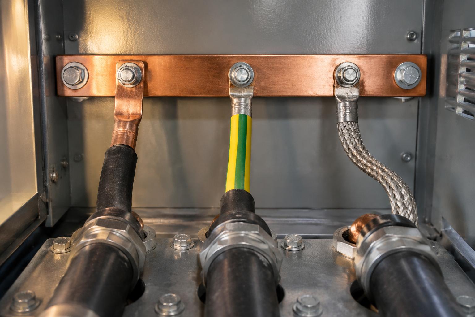
What Does Switchgear Earthing Actually Consist Of?
It helps to separate three layers that are often conflated in a tender document.
| What it is | What it is for | Who normally supplies it | |
|---|---|---|---|
| Protective bonding inside the assembly | The main earthing bar, plus the bonds from frames, doors, gland plates, screens and instrument-transformer cases to that bar | Keeps every touchable metal part at the same potential during a fault, so that fault current returns by a known path | The switchgear manufacturer |
| Earthing points and earthing switches | The make-proof earthing switch in each feeder, its connection to the bar, and the interlock that governs it | Provides a visible, rated earth on a circuit that is being worked on | The switchgear manufacturer |
| Site earthing system | The earthing conductors, electrodes and mesh that connect the assembly to the general mass of earth | Carries the fault current into the ground and controls touch and step voltage at the installation | The installation contractor, to the installation standard |
The boundary between the second and third layers is where responsibility is most often blurred. The manufacturer's bar has to be connected to the site system by someone, and that connection is a design item: its route, its protection against mechanical damage and its test point all belong in the installation drawing, not in a site instruction on the day of energisation.
Why Is the Main Earthing Bar the Backbone?
A main earthing bar is a continuous copper conductor, usually rectangular, that runs the length of the switchgear and is accessible in each compartment. Everything that needs an earth connects to it: the enclosure frame, the removable panels, the cable gland plate, the cable screens, the instrument transformer cases and the earthing switch. Because it is one conductor, the potential difference between any two bonded parts during a fault is small, and the touch voltage across a person standing at the panel is correspondingly small.
The bar's job also makes it a commissioning tool. With everything landed on one bar, an earth continuity test becomes a short, repeatable measurement from a known reference to each part, and a high reading points to a specific bond rather than to a general suspicion. That is why the bar is normally fitted with dedicated test points and why the connection to the site earth is made through a disconnectable link or a test joint rather than a welded joint that cannot be opened.
Manufacturers describe the bar as running through the cable termination compartments of the panels, which is deliberate: the cable screens are the largest and least controllable source of fault current entering the assembly, so the bar is routed to meet them where they arrive.
How Are Cable Screens, Glands and Frames Bonded?
The cable screen is the connection that is most often got wrong, because it is also a circuit element. On a three-core cable the screen is a metallic tape or wire layer over the insulated cores, and it is bonded to the earthing bar at the termination. On a single-core cable each core has its own metallic screen, and the bonding arrangement becomes a design decision: bonding at both ends creates a closed loop in which the screen current circulates, while bonding at one end leaves a standing voltage on the screen at the other.
Which arrangement is correct depends on the cable length, the fault current and the screen's withstand, and it is decided by the cable system design, not by the switchgear supplier. What the switchgear has to provide is a reliable, accessible bonding point and enough space to make the connection properly. The single-core trefoil guide covers the arrangement and the screen-voltage consequences in more detail.
Two bonding details recur in inspection reports. The first is the gland plate: if it is painted and bolted to a painted frame, the bond depends on the paint film. A dedicated bonding conductor or a star washer under a masked joint is the fix, and it should be shown on the drawing rather than left to the installer. The second is the door: a hinged door with a painted hinge and no braid is not bonded, even though it looks continuous.
Inside the assembly, the principle is that all high-voltage parts are either metal-enclosed or provided with earthed layers. A manufacturer's design description for a gas-insulated secondary distribution panel states exactly that for cable terminations, busbars and voltage transformers, and adds that the cable and fuse compartments are accessible only when the outgoing feeders are earthed. The earthed layer is doing the same job as the bar: it puts a conductive surface between the operator and the live part, and it carries the capacitive current that would otherwise appear on the enclosure.
What Does the Earthing Switch Add?
Protective bonding makes the enclosure safe to touch while the equipment is in service. An earthing switch does something different: it connects a circuit that has been isolated to earth, so that the conductors being worked on cannot become live through induction, back-feed or a mistake.
The distinction between the two devices is worth keeping because their ratings are different. A protective bond carries fault current for the duration of the fault; an earthing switch must be able to make onto a live circuit in the worst credible case, which is why the make-proof (fault-making) rating is specified separately from the short-time withstand rating. The earthing switch guide covers those ratings and the interlock logic in detail.
The interlock is the part that turns a device into a procedure. In the gas-insulated panel example above, the compartment cannot be opened until the feeder is earthed; the earthing switch in turn cannot be closed unless the switching device is open. Each step depends on the previous one, and the operator's voltage check sits at the front of the chain. That is why a missing or painted-over voltage indicator undermines the earthing system as a whole.
Why Does Touch Voltage Matter More Than Earth Resistance?
A single earth resistance reading says very little about whether a person standing at the panel is safe. What matters is the voltage that appears between the metalwork a person can touch and the ground they are standing on while fault current is flowing. That is touch voltage, and it depends on the impedance of the return path and on the geometry of the earthing system, not on one electrode's resistance.
Practical guidance on switchgear grounding makes the point that touch voltage can be the greater hazard, and that in compact installations the bonding network has to do more of the work because there is less site area to dissipate current. The recommended practice is a mesh with many short interconnections rather than a few long conductors: short grounding conductors, a mesh bonded to the building steel, and multiple bonds along the enclosure so that fault current has parallel paths and the potential rise is shared.
Three of those practices transfer directly to a 10–35 kV switchroom, even where the equipment is air-insulated rather than gas-insulated:
- Keep earthing conductors short and direct. A long, looping bond has impedance and picks up induced voltage
- Bond the building steel and support structures. A floating steel frame next to a faulted panel can sit at a different potential from the panel
- Bond secondary cable shields at both ends where the practice requires it, to reduce interference and avoid a floating shield acting as an antenna
The last point is separate from the primary cable screen question and is often confused with it. A secondary control cable shield bonded at both ends is normal practice for interference control; a single-core primary cable screen bonded at both ends creates a circulating current. Same word, different circuit, opposite answer.
How Is Switchgear Earthing Verified at Commissioning?
Verification is mostly visual and continuity work, and it should be done before the panel is energised, not after.
- Walk the bar. Confirm that it is continuous through every panel, that joints are accessible and that the connection to the site earth is made and can be isolated for testing
- Measure continuity to each bonded part. Frames, doors, gland plates, screens and instrument-transformer cases, measured from the bar. A high reading is a finding, not a rounding error
- Inspect the joints. Paint, corrosion and loose bolts are the three failure modes. Confirm that bonding surfaces were masked before painting and that the bolts are torqued to the manufacturer's figure
- Operate the earthing switch. Confirm that it closes and opens freely, that the interlock prevents the prohibited sequence, and that the position indicator agrees with the actual state
- Record the arrangement. Cable screen bonding method, test-point locations and the site-earth connection point belong in the handover file, because the next person to work on the panel will need them
The installation standard that governs the site side of this work is IEC 61936-1, which sets requirements for the design and erection of electrical power installations in systems with nominal voltages exceeding 1 kV AC. The switchgear is one component within that installation, and the earthing design has to satisfy the installation standard as a whole rather than the panel alone.
What Should a Specification State About Switchgear Earthing?
A specification that prevents the common failures states the following, and leaves the values to the fault study.
| What to state | Why | |
|---|---|---|
| Main earthing bar | Material, continuous through all panels, accessible in each compartment, with test points and a disconnectable link to the site earth | Makes the system testable and gives every bond one reference |
| Bar rating | Sized for the prospective fault current and its duration, stated as a pair | A current without a duration is not a rating |
| Bonding | Every removable panel, door, gland plate and instrument-transformer case bonded by a dedicated conductor, with paint removed at the joint | Painting after assembly is the most common cause of a lost bond |
| Cable screens | Bonding arrangement stated per cable type, with the decision on single-core screens recorded | The supplier cannot choose the cable system's bonding method for the designer |
| Earthing switch | Fault-making rating, short-time withstand current and duration, interlock scheme | The switch must be rated for the worst-case close, not just the steady state |
| Labels and drawings | Earthing points labelled, as-built earthing drawing supplied | Maintenance and future extension depend on knowing what is bonded to what |
Six Mistakes That Recur
- Bonding through paint. A gland plate or door bolted to a painted frame is not bonded, however tight the bolts are
- One bond for a whole row of panels. Each panel needs its own connection to the bar, not a shared jumper at the end of the row
- Screen bonding decided on site. Whether a single-core screen is bonded at one end or both is a design decision with a voltage consequence, not an installer's preference
- Earthing switch treated as a bond. The switch earths a circuit for work; it is not the protective bonding of the enclosure, and its ratings are different
- No test point. A welded or buried connection cannot be verified later, which removes the only practical way to prove the chain is intact
- Ignoring the building steel. A support structure that is not bonded can sit at a different potential from the panel it carries
Frequently Asked Questions About Switchgear Earthing
What is switchgear earthing in simple terms?
It is the network of conductors that connects every metal part of the switchgear — frames, doors, cable screens, earthing switches — to the site earth, so that fault current has a known path and the metalwork stays safe to touch.
What is the main earthing bar for?
It is the common reference conductor that runs through the switchgear. Every bond lands on it, which keeps all bonded parts at nearly the same potential during a fault and makes earth continuity testing a short, repeatable measurement.
Is an earthing switch the same as protective bonding?
No. Protective bonding keeps the enclosure safe while the equipment is in service. An earthing switch connects an isolated circuit to earth so it can be worked on, and it needs a fault-making rating because it may have to close onto a live circuit.
Should a cable screen be earthed at one end or both?
It depends on the cable system. For single-core cables, bonding both ends creates a closed loop with circulating screen current, while single-point bonding leaves a standing voltage at the far end. The choice belongs to the cable system design, and the switchgear must provide the bonding point the design requires.
Why is touch voltage more important than earth resistance?
Because safety depends on the voltage across a person standing at the panel during a fault, not on a single electrode reading. Touch voltage is governed by the impedance of the return path and by how well the metalwork is bonded, which is why short conductors and a mesh outperform a few long electrodes.
How is switchgear earthing tested?
By visual inspection of joints and bonding surfaces, followed by continuity measurements from the main earthing bar to each bonded part, and by operating the earthing switch and its interlock. The results are recorded against the as-built drawing.
Which standard covers earthing of an MV installation?
IEC 61936-1 sets requirements for the design and erection of electrical power installations in systems with nominal voltages exceeding 1 kV AC. Switchgear earthing is one part of that installation, and the site earthing design has to satisfy it as a whole.
Does a higher IP rating remove the need for bonding?
No. Ingress protection limits dust and water; it says nothing about fault current or touch voltage. An IP65 enclosure still needs a bonded frame, a main earthing bar and a tested connection to the site earth.
Sources and Further Reading
- Siemens — Switchgear Type 8DJH, catalog HA 40.2 (2022) — earthed layers on high-voltage parts, make-proof feeder earthing switches, compartment access only when earthed, and IEC 61936-1 / EN 50522 in the standards table
- Electrical Engineering Portal — Practical lesson in grounding and bonding of Gas-Insulated Switchgear — touch voltage, multipoint bonding, short grounding conductors, bonding of steel structures and secondary cable shields
- DS/EN IEC 61936-1:2021 — Power installations exceeding 1 kV AC — scope of the installation standard that governs the site earthing design
Switchgear earthing is not a single component that can be bought and fitted. It is a chain of connections, each of which is simple and none of which tolerates an assumption: a bar with test points, a bond on every removable part, a screen bonding method that matches the cable system, an earthing switch with the right making rating, and a tested connection to the site earth.
Nahu Group supplies earthing switches, metal-enclosed cabinets, ring main units and metering boxes for 10–35 kV distribution, with the main earthing bar and bonding points arranged to the project drawing. If a specification leaves the bar rating or the screen bonding method open, send it across and we will show which lines need a value before the panel is released for manufacture.
Published October 20, 2026 · Nahu Group (NAHU Electric Technology)