Every kilowatt-hour that leaves a distribution line has to be measured — and on medium-voltage feeders, the measurement point is usually a high-voltage metering box. It combines the current transformers, voltage transformers and a sealed meter compartment into a single weatherproof unit that converts a 10–35 kV circuit into an accurate, tamper-resistant billing point.
For utilities and industrial consumers, the metering box is the device that decides how much is billed. Understanding how it works, what the model designations mean, and how to match one to your network is the difference between a billing point that is accurate for decades and one that loses revenue or fails an inspection from day one.
What Is a High-Voltage Metering Box?
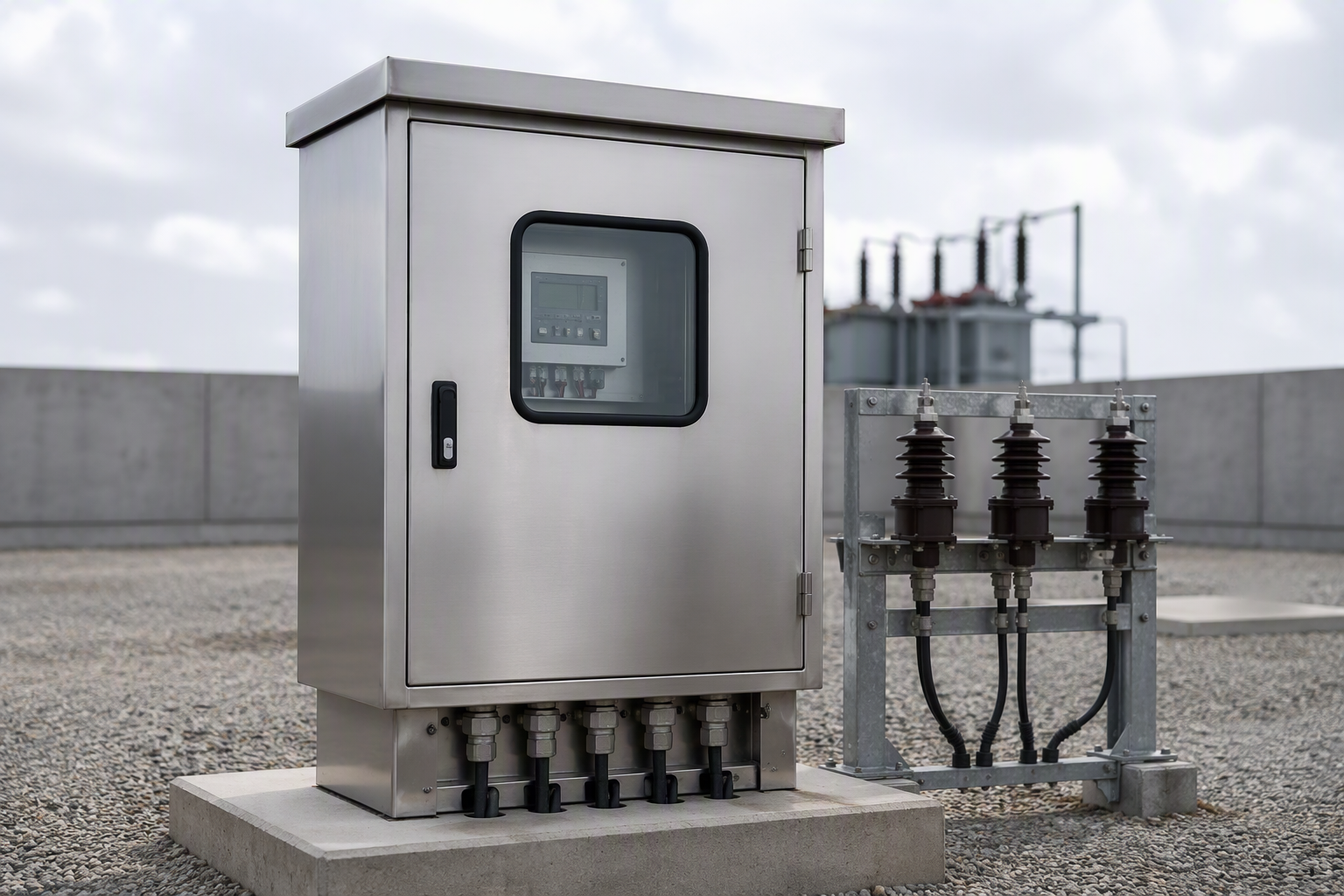
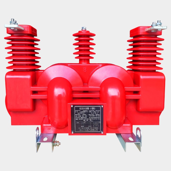
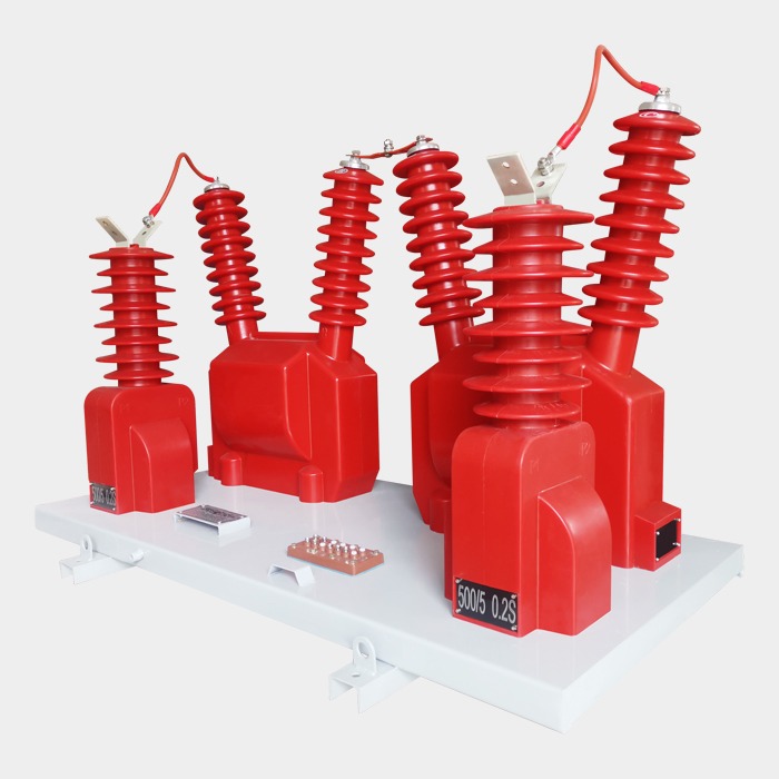
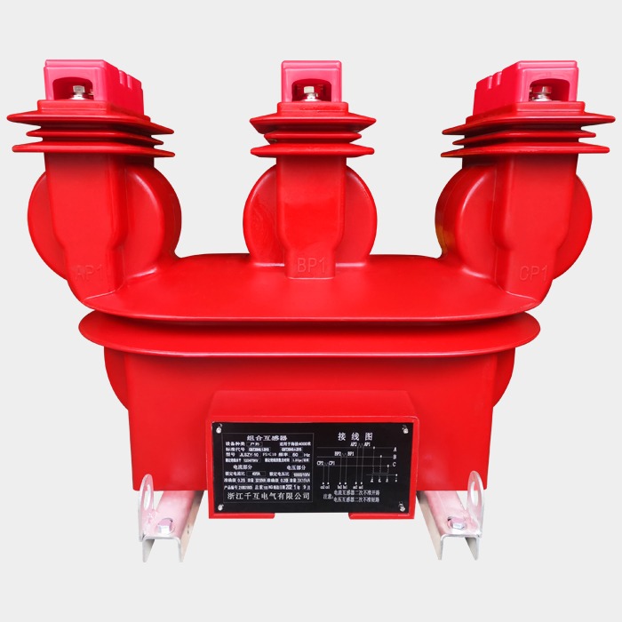
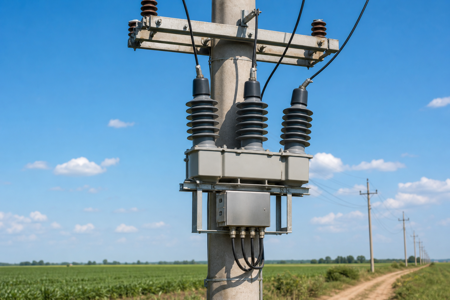
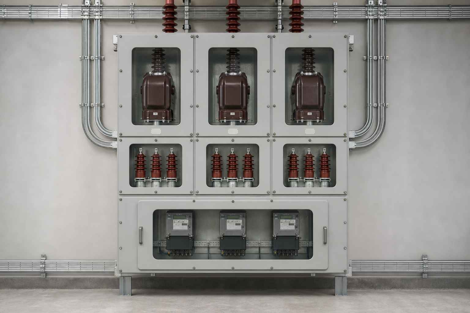
A high-voltage metering box — also called a combined metering unit — is a single enclosure that integrates two current transformers, two voltage transformers and a meter compartment. It is installed directly in the high-voltage circuit and is used for revenue metering on 10–35 kV distribution lines, transformer substations and large consumer connections.
The box performs three jobs in one: it steps the line current down to a measurable secondary value, steps the line voltage down to a safe secondary value, and houses the energy meter (or provides sealed terminals for it) where the two are multiplied into consumption. Because everything is factory-assembled, tested and sealed together, the metering ratio is fixed and certified — which is exactly what a billing point needs.
How a Metering Box Works
A three-phase metering box measures power using the V/V connection: two current transformers on phases A and C, and two voltage transformers connected across A–B and C–B. This two-element scheme is the standard for three-phase three-wire metering and is used across the vast majority of 10–35 kV installations because it measures the true power of an ungrounded or lightly grounded system with only two of each transformer.
- Current transformers step the primary current down to a 5 A or 1 A secondary at a fixed ratio, such as 100/5 A or 600/5 A
- Voltage transformers step the primary voltage down to a 100 V secondary (100/√3 V in some connections), such as 10,000/100 V
- The meter multiplies the sampled current and voltage to register kilowatt-hours and, with phase information, reactive energy as well
Accuracy is expressed in classes. For revenue billing, the instrument transformers are specified at 0.2S or 0.5S — the "S" denoting an extended current range down to 1% of rated current, where most real-world loads actually sit. Metering cores are wound for low burden and high accuracy, while a separate protection core (typically class 5P or 10P) can be included to feed protective relays without disturbing the metering circuit.
Main Types of High-Voltage Metering Boxes
Nahu Group manufactures the JLS series of combined metering units, covering the common 10 kV and 35 kV classes:
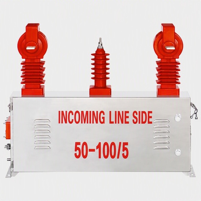
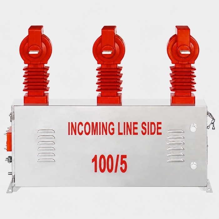
- JLSGWV-10 — outdoor 10 kV metering box, dry-type combined cast-resin construction, pole-mounted
- JLSGWY-10 — outdoor 10 kV metering box with oil-immersed transformers for heavier duty and long service life
- JLSZV-10 — outdoor 10 kV metering box, dry cast-resin design with compact dimensions
- JLSZV-35 — outdoor 35 kV metering box for sub-transmission and large industrial metering points
- JLSZY-10 — outdoor 10 kV metering box with enhanced creepage and pollution performance for coastal and industrial atmospheres
Construction splits into two families. Dry, combined cast-resin units mould the CT and VT windings into epoxy housings — lighter, maintenance-free and safer to handle — while oil-immersed units provide generous thermal margin and are preferred where high sustained loads or harsh conditions demand the extra ruggedness. Mounting is either directly on the pole (pole-mounted) or on a platform with the box above the working height (platform-mounted). Enclosures are rated IP66 or better, so the meter compartment and terminations stay dry through decades of outdoor service.
Wiring and Polarity
Correct wiring starts with polarity. On each current transformer, the primary terminal marked P1 faces the source and P2 faces the load, so the secondary terminals S1 and S2 produce the correct phase relationship for the meter. Reversing P1/P2, or swapping S1 and S2 on one phase, inverts that phase's current and corrupts the energy reading — often by a huge margin that is invisible until the meter is checked.
- Never open a current transformer secondary while the primary is energised — the secondary would rise to a dangerous voltage and the core could saturate or flash over
- Fit shorting links on the CT secondary terminals and close them before disconnecting the meter wiring
- Earthing of the secondary circuits must be done at one point only — usually the meter compartment or the first terminal — to avoid circulating currents
- Voltage transformer fuses must be present and correctly rated; a VT secondary short circuit is a serious fault
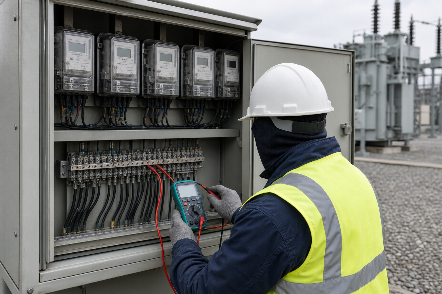
Secondary wiring should be twisted or screened, terminated with proper ferrules, and labelled phase by phase. A clean, documented wiring scheme is also what makes commissioning tests — ratio check, polarity check and phase-sequence check — fast and unambiguous.
How to Choose a Metering Box
Selection is a checklist, and every line on it is a hard requirement for the utility's approval:
- System voltage — 10 kV or 35 kV class must match the network; the VT primary ratio follows the nominal voltage (e.g. 10,000/100 V)
- Primary current ratio — sized from the load: the CT should carry the normal load at 50–80% of its rated current for best accuracy
- Accuracy class — 0.2S or 0.5S for metering cores, plus a 5P/10P protection core if relays share the unit
- Burden — the VA rating of the meter plus lead losses must not exceed the transformer's rated burden, or accuracy degrades
- Insulation type — dry cast-resin for lightweight, maintenance-free service; oil-immersed where thermal margin and ruggedness dominate
- Enclosure — IP66-rated housing and a sealable meter compartment with provisions for utility seals, for tamper resistance
- Compliance — specify to IEC 61869 (instrument transformers) so the unit is accepted by the network operator
Do not undersize the CT ratio "because the load will grow". An oversized CT meters the early years of a small load in the least accurate part of its range, and retrofitting a sealed metering unit later costs far more than choosing correctly the first time.
Installation and Commissioning
Installation begins with a sound mechanical mount and clearances that follow the manufacturer's drawing, followed by the wiring discipline described above. Commissioning then verifies the whole chain: ratio and polarity of each transformer, secondary wiring continuity, phase sequence at the meter, and the accuracy of the energy reading against a reference. Our field guides cover the process in detail — see installing and wiring a high-voltage metering box and the instrument transformer site testing checklist.
Maintenance
A metering box is a long-life asset, but it is also a revenue instrument, so it deserves periodic attention: visual inspection for cracked resin, corrosion and vermin entry; confirmation that seals are intact and untampered; check of secondary connections and shorting links for tightness; and verification that the earthing conductor is sound. Instrument transformers for billing are normally re-verified at intervals set by the utility — commonly every five to ten years, or after any fault that could have stressed the windings.
Q&A
Question: What is the difference between a metering box and separate CTs plus VTs?
Short answer: A metering box integrates both transformer sets and a sealed meter compartment in one factory-tested enclosure with fixed, certified ratios. Separate CTs and VTs give flexibility for unusual installations but require on-site wiring, separate sealing and more space.
Question: What does the V/V connection mean?
Short answer: It is a two-wattmeter measurement using two current transformers (phases A and C) and two voltage transformers (A–B and C–B). It measures true three-phase power in three-wire systems with only two of each transformer, which is why it is standard in 10–35 kV metering.
Question: What happens if a CT secondary is opened under load?
Short answer: The secondary voltage rises sharply — potentially to thousands of volts — with a risk of flashover, insulation damage and danger to personnel. Short the secondary or de-energise the primary before disconnecting anything.
Question: How often should metering accuracy be re-verified?
Short answer: Typically every 5–10 years, or per the utility's metering code, plus after any severe fault or suspected tampering. Class 0.2S/0.5S transformers hold accuracy well, but seals and connections should be checked more frequently.
Nahu Group (NAHU Electric) manufactures JLS-series metering boxes for 10–35 kV revenue metering — JLSGWV, JLSGWY, JLSZV and JLSZY outdoor units with dry cast-resin or oil-immersed transformers, sealed meter compartments and IEC 61869 compliance. For ratios, accuracy classes and approval support, see our metering box range, or contact our engineering team.
Published August 20, 2026 · Nahu Group (NAHU Electric Technology)