
Surge arrester grounding is where the protection margin bought at the quotation stage is most often spent, because a good residual voltage is easy to specify and a long earth lead is easy to inherit from the layout. The arrester clamps at its own terminals; the equipment it protects sees that clamp plus everything the phase lead and the earth lead add on the way.
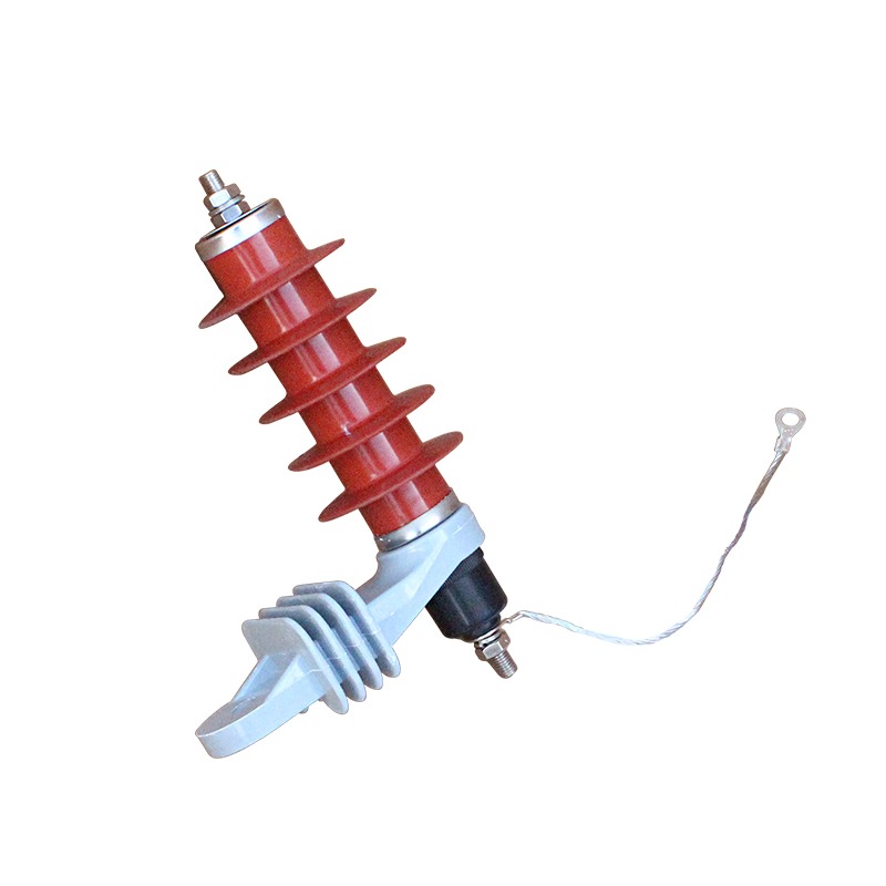
Why Does Surge Arrester Grounding Set the Protection Level?
An arrester works by diverting current, and diverted current has to reach earth through a conductor. That conductor is part of the circuit, not an accessory to it: its inductance sits in series with the discharge, and its resistance sits between the arrester base and the reference the equipment is earthed to.
This is why the same arrester performs differently in two installations. IEC 60099-4 defines the rated voltage, the continuous operating voltage and the residual voltage limits, and those are the numbers on the datasheet. None of them describes the earthing arrangement at the site, which is why the installation drawing decides the protection level the transformer actually receives.
What Earth Resistance Should the Arrester See?
A power-frequency resistance measurement is a proxy for something faster. The surge sees the impedance of the electrode and of every joint between the arrester base and the equipment earth. Utilities specify an ohmic value because it is measurable; the values below reflect common practice, not a single international number.
| Arrangement | Value commonly specified | What it is really controlling |
|---|---|---|
| Bonded to a substation earth grid | The grid value, typically 1 Ω or less at power frequency | One reference shared with the transformer, with no potential difference during the discharge |
| Pole-mounted unit with its own electrode | Commonly 10 Ω or less; some utilities ask for 5 Ω | The length and condition of the down lead more than the rod itself |
| Line arrester on a rural spur | Values of 25 Ω and above appear in utility practice | An accepted compromise, paid for by a higher voltage at the equipment |
Continuity matters more than the number on the test sheet. A 2 Ω reading at the rod proves nothing if the lug above it is bolted to powder-coated steel, and a 1 Ω grid is no help if the surge arrester grounding conductor runs to a separate rod two metres away. That separate rod is the most common defect: it creates a loop the surge uses to travel through the building.
How Much Voltage Does One Metre of Lead Add?
A lead has roughly one microhenry per metre. Multiply by the rate of rise of the discharge current and the result is the voltage the lead drops during the surge, added directly to the residual voltage. The arithmetic is short enough to put on a drawing note, which is why it should be.
| Current steepness | 0.5 m of lead | 1 m of lead | 2 m of lead |
|---|---|---|---|
| 5 kA/µs | 2.5 kV | 5 kV | 10 kV |
| 10 kA/µs | 5 kV | 10 kV | 20 kV |
| 20 kA/µs | 10 kV | 20 kV | 40 kV |
Take a 10 kV rated arrester with a 30 kV residual voltage at 5 kA, mounted 1.5 m from the transformer terminal at a 10 kA/µs steepness: the equipment sees roughly 45 kV. On an 11 kV winding with a lightning impulse withstand level of 75 to 95 kV that still leaves margin, but the margin is now halved by installation detail.
How Far Can the Arrester Sit From the Protected Equipment?
There is no single permitted distance, and any figure quoted without the steepness and the withstand level attached is arbitrary. The workable rule is to mount the arrester on the equipment it protects: on the transformer tank, at the cable termination, on the switchgear panel, at the riser pole. Where a separate structure is unavoidable, keep the loop from phase terminal through the arrester and back to the equipment earth short.
Which terminal the arrester is connected to is a separate decision, and it changes the voltage seen in service rather than the lead length; the three options are set out in surge arrester connection methods.
What Changes With Drop-Out and Gap-Type Arresters?
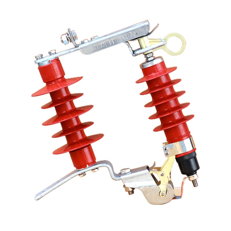
On a drop-out arrester the unit disconnects itself after a failure, which puts a hinge and a disconnecting link inside the earth circuit. Those parts must stay clean and free to operate, because a corroded hinge adds a resistance no test sheet will show.
An external-gap design, such as the piercing type used on insulated overhead conductors, isolates the varistor behind a series gap in normal service. That removes continuous leakage through the earth connection and tolerates a higher earth resistance between surges, but the discharge still travels through the gap and the full earth lead. The choice between types is covered in the lightning arrester type and selection guide.
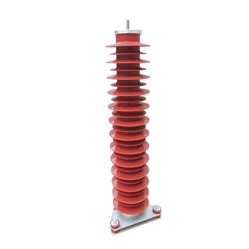
A gapless metal-oxide unit with a composite housing behaves the opposite way: it conducts a small leakage current continuously, so a high-resistance earth joint runs warm in normal service and can fail before any surge arrives. On those units the earth stud, the lug and the bolt torque are worth checking at every routine visit.
Which Grounding Mistakes Fail an Inspection?
Most surge arrester grounding defects are cheap to fix before energisation and expensive afterwards:
- A separate earth rod. It creates a second reference and a loop the surge will use.
- A long earth lead run for neatness. Two extra metres can remove the arrester from the circuit at high steepness.
- Earth terminals daisy-chained. Each joint adds resistance and hides the next one's condition.
- Conductor undersized for the discharge current the arrester is rated to pass.
- Paint under the lug. The joint reads open on a continuity test and looks perfectly bolted.
- Lead left disconnected after a test. Common where no isolator was provided; what a counter records between visits is covered in arrester monitoring with a surge counter.
What Should the RFQ State?
Arresters are usually bought on four numbers and installed on assumptions. These lines close that gap; the service conditions they sit inside are defined in IEC 62271-1:
- System voltage and earthing arrangement, because earth fault duration decides rated voltage and continuous operating voltage.
- Rated voltage, continuous operating voltage and nominal discharge current, with residual voltage at that current.
- Mounting position and available lead length, on the drawing rather than in a covering letter.
- Earth terminal size, material and bolt torque, plus the conductor the site will use.
- Documents: type test report to IEC 60099-4, routine test report, installation drawing showing the earth bond.
Where Nahu Group Fits
Nahu Group supplies composite and zinc-oxide arresters for 10 to 35 kV systems, including the YH and HY composite arrester range with a single base earth stud, the YH5WS-TB drop-out arrester for pole mounting, and the piercing-type external gap arrester for insulated overhead conductors.
To get a configuration, send the system voltage and earthing arrangement, the equipment being protected and its withstand level, the mounting position with the lead length available, the fault level at the point of installation and the pollution level. With those details the rated voltage, the residual voltage class and the earth terminal arrangement can be confirmed against the drawing before the order is placed.
Frequently Asked Questions About Surge Arrester Grounding
What earth resistance does a surge arrester need?
It depends on the arrangement, not the arrester: 1 Ω or less where it bonds to a substation grid, commonly 10 Ω or less on a pole with its own electrode, higher on rural spurs. Continuity and a single earth reference matter more than the reading.
How much protection does a long arrester earth lead cost?
Roughly 1 µH per metre, so 10 kV per metre at a steepness of 10 kA/µs, added directly to the residual voltage the equipment sees. Two metres of lead on a 10 kV arrester can add 20 kV, which is the difference between a comfortable margin and none at all.
Can an arrester have its own earth electrode?
It should not, where the protected equipment has its own earth. Two electrodes create two references, and the surge finds the difference through the building. The arrester earth belongs on the equipment earth by the shortest route, with the conductor sized for the discharge current rather than for the continuous rating.
Where should the arrester be mounted relative to the transformer?
On the transformer, at its tank or terminal box, rather than on a convenient wall or structure nearby. Where a separate structure is unavoidable, the loop through the arrester and back to the equipment earth has to stay short.
Does a gap-type arrester need the same earthing as a gapless one?
The earth connection carries the same discharge current, so it needs the same conductor and bond. What changes is normal service: a gapless metal-oxide unit conducts a small leakage current continuously and overheats at a poor joint, while a gapped unit tolerates higher resistance between surges.
Sources and Further Reading
- IEC 60099-4:2014 — Surge arresters, Part 4: Metal-oxide surge arresters without gaps for a.c. systems — rated voltage, continuous operating voltage, residual voltage limits and the line discharge class that the earth connection has to carry
- IEC 62271-1:2017 — High-voltage switchgear and controlgear, Part 1: Common specifications for alternating current switchgear and controlgear — the service conditions, pollution levels and earthing-terminal requirements of the assembly the arrester is mounted on
Published Nov 11, 2026 · Nahu Group (NAHU Electric Technology)