
A surge arrester is a voltage-dependent resistor with one job: clamp the surge below the insulation level of what it protects. Whether it succeeds depends less on the arrester than on where its two terminals are connected. The same unit, moved from phase-to-ground to phase-to-phase, changes both the continuous voltage it sees and the insulation it protects.
Three connections cover nearly every distribution application. Phase-to-ground protects the insulation from conductor to earth. Phase-to-phase protects the insulation between conductors, and is the answer where no neutral exists. Neutral-to-ground protects the winding and the neutral insulation of a transformer. Each has a different selection rule, and confusing them is one of the quieter ways a protection scheme fails to protect anything.
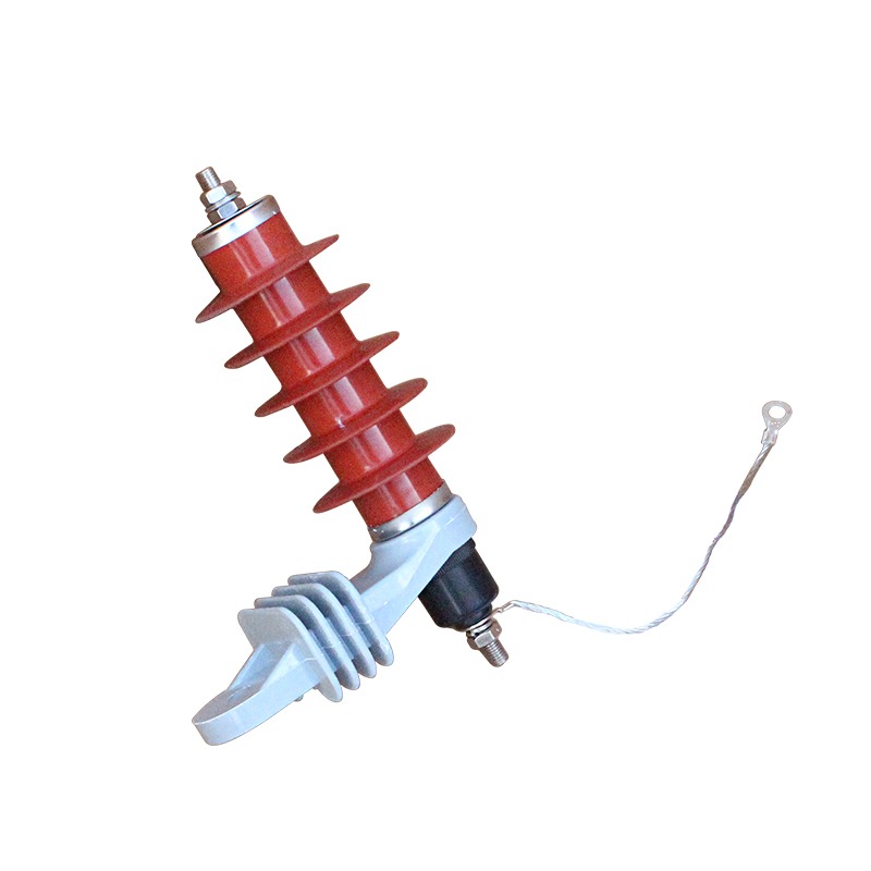
The Three Connections at a Glance
| Connection | Arresters per set | What it protects | Typical application |
|---|---|---|---|
| Phase-to-ground | Three, one per phase | Phase-to-earth insulation of cables, windings, switchgear | Effectively earthed and resistance-earthed MV networks |
| Phase-to-phase | Two or three, depending on arrangement | Insulation between phases | Three-wire delta systems, motor and capacitor circuits |
| Neutral-to-ground | One, at the transformer neutral | Neutral insulation and winding end insulation | Earthed transformer neutrals, generator neutrals |
The table hides the important part: the continuous voltage that appears across the arrester is different in each case, and the arrester must be selected for the voltage it will actually see rather than for the system voltage written on the drawing.
Phase-to-Ground: The Default for Distribution
One arrester per phase, from conductor to the station earth bar. This is the arrangement in almost every medium-voltage cubicle, because the insulation that surges damage most often is the insulation from conductor to earth: cable insulation, bushing surfaces, transformer windings, the air gap between a phase and the earthed enclosure.
Selection starts from the continuous operating voltage. In an effectively earthed system the phase-to-earth voltage during a single-phase earth fault rises only modestly, and a continuous voltage rating of about 1.25 times the maximum phase-to-earth voltage is the usual starting point. In an isolated or resonant-earthed system, a single earth fault leaves the healthy phases at full phase-to-phase voltage for as long as the fault persists, so the arrester has to be rated for that condition instead - a materially higher continuous voltage rating for the same system voltage.
This is the single most common specification error in arrester selection: an arrester chosen by system voltage alone, without asking how long the network can run with one phase earthed. The lightning arrester guide sets out the rest of the selection chain.
Phase-to-Phase: When There Is No Neutral to Protect
In a three-wire delta system the neutral is either absent or deliberately unearthed, and the insulation that matters is between phases. Arresters connected phase-to-phase clamp the voltage difference between two conductors, and each unit continuously sees the full phase-to-phase voltage rather than the phase-to-earth voltage.
That difference in continuous voltage is why a phase-to-ground unit cannot simply be reused between phases. An arrester rated for phase-to-earth duty in an 11 kV system is not rated for the 11 kV that will sit across it in a phase-to-phase connection; the result is a unit that conducts continuously, overheats and fails - usually without any surge having occurred.
Phase-to-phase connection is also used alongside, not instead of, phase-to-ground units where both insulation systems need protection, for example at the terminals of a large motor on an unearthed system where the winding insulation to earth and the insulation between phases are both at risk.
Neutral-to-Ground: Protecting the Winding, Not the Phase
A transformer neutral is a point of the winding, and it has insulation of its own. When a surge arrives through the phase terminals, the voltage distribution along the winding is not uniform, and the neutral end can see a voltage that the phase-to-ground arresters do nothing about. An arrester from neutral to earth limits that voltage, and in doing so also limits the potential rise of the neutral during an earth fault elsewhere on the network.
The selection rule differs again. The continuous voltage across a neutral-to-ground arrester is normally small in an earthed system and can be significant in a system where the neutral is displaced during earth faults, so the rating follows the earthing arrangement rather than the phase voltage. Where the neutral is brought out through a current transformer for earth fault protection, the arrester earth connection and the CT secondary wiring must not share a path.
Matching the Connection to the Earthing System
| Earthing arrangement | Phase-to-earth voltage during an earth fault | Practical consequence for the arrester |
|---|---|---|
| Effectively earthed | Rises modestly, cleared quickly | Standard phase-to-ground arrester rated near 1.25 times the phase-to-earth voltage |
| Resistance earthed | Rises, cleared by the resistor-limited current | Same connection; check the fault duration against the arrester thermal rating |
| Isolated or resonant earthed | Healthy phases reach full phase-to-phase voltage and stay there | Phase-to-ground arrester rated for the higher continuous voltage, or phase-to-phase arrangement in a delta system |
The duration column matters as much as the voltage. An arrester is a resistor that absorbs energy, and an earth fault that is allowed to persist for hours delivers energy continuously. Where the network is operated with an earth fault alarm rather than an earth fault trip, the arrester has to be able to survive that condition, which is a thermal question rather than a voltage question.
Lead Length Adds Kilovolts to the Protection Level
The arrester clamps the voltage at its own terminals. The equipment it protects is somewhere else, connected by leads, and those leads are inductance. The voltage arriving at the equipment is the arrester residual voltage plus L × di/dt along the connection.
With roughly one microhenry per metre of lead and a surge steepness of ten kiloamperes per microsecond, each metre of lead adds about ten kilovolts. An arrester with a 20 kV residual voltage on a one-metre lead presents 30 kV to the equipment - and the insulation level of an 11 kV transformer may be only a little above that. On a two-metre lead the arrester has been effectively removed from the circuit.
Three practical rules follow, and they cost nothing to apply at installation:
- Mount the arrester on the equipment it protects - on the transformer tank, at the cable termination, on the switchgear panel - rather than in a convenient row on the wall.
- Run the phase lead and the earth lead together and as short as possible. Their inductances add; keeping them parallel and close reduces the loop area.
- Bond the arrester earth to the equipment earth by the shortest route, and never by a separate earth rod. Two earth paths create a loop that the surge will use.
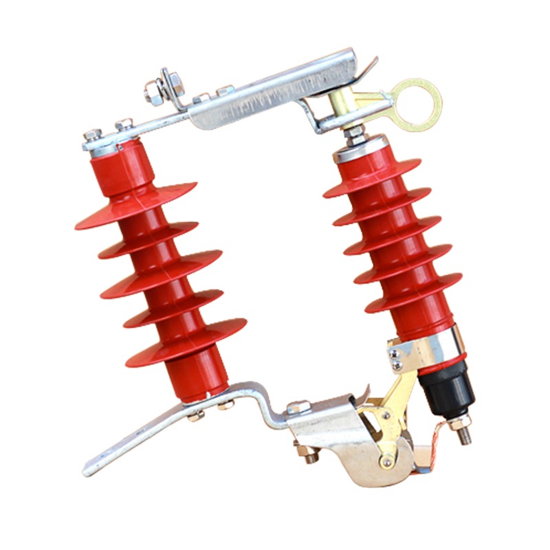
Gapless and Gapped Arresters: A Different Connection Consideration
In a gapless metal-oxide arrester the varistor is permanently connected, conducting a small leakage current that is designed for. In a gapped design, an external or internal series gap isolates the varistor in normal service, and the gap flashes over when the voltage rises - the form still common on overhead lines, including drop-out types that can be replaced from a pole without tools.
The connection implication is in the earthing. A gapless arrester with a poor earth is worse than a gapped one, because its continuous leakage current flows through the earth connection and a high-resistance joint will run hot and eventually fail. A gapped arrester tolerates a higher earth resistance in normal service but depends on a lower one during the surge itself.
Mistakes That Show Up After the First Storm
- Arresters selected by system voltage alone. The continuous voltage rating is decided by the earthing system and the earth fault duration, not by the nominal voltage.
- Phase-to-ground units used in phase-to-phase duty. The units conduct continuously and fail thermally, often within days.
- A separate earth rod for the arrester. The surge then travels through the building to reach the equipment it was meant to protect.
- Long leads to a better location. A neat installation two metres from the transformer is a worse installation than a crowded one on the tank.
- No isolator or disconnector. An arrester that fails short-circuit cannot be isolated for testing without taking the circuit out, and a failed unit is usually only discovered when the circuit trips.
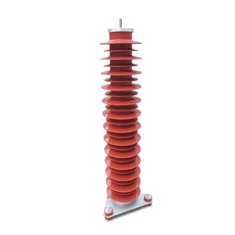
What to Write on the Specification
Four lines settle the connection question in most inquiries: system voltage and earthing arrangement, the equipment being protected, the insulation level of that equipment, and the mounting position relative to it. Add whether the network may run with one phase earthed, and the continuous voltage rating follows without argument.
The surge arrester range covers gapless metal-oxide and external-gap types for pole and cubicle mounting, and because the arrester and the distribution cabinets that house it come from the same factory, the mounting position and lead length can be agreed before the enclosure is built. The insulator range covers the creepage requirement of the same polluted or coastal sites.
A surge arrester is judged on the day of the storm, when nobody is watching. The connection method and the length of its leads decide whether that day is an event or an incident.
Frequently Asked Questions About Arrester Connection
Which arrester connection is used most often in distribution?
Phase-to-ground, one arrester per phase, connected between the phase conductor and the station earth. It is the default in effectively earthed and resistance-earthed medium-voltage networks because the phase-to-earth insulation of the transformer, the cables and the switchgear is what a surge most often threatens.
When is a phase-to-phase arrester connection used?
On systems where the neutral is not available or is not earthed, such as three-wire delta arrangements, and where the insulation between phases rather than to earth is the weak point, for example certain motor and capacitor applications. Phase-to-phase arresters see a different continuous voltage from phase-to-ground units and must be selected for it.
Why connect an arrester between the transformer neutral and earth?
To limit the voltage that appears across the neutral insulation and the winding when a surge arrives through the phase connections or when an earth fault elsewhere raises the neutral potential. It complements, rather than replaces, the phase-to-ground arresters that protect the winding ends.
How much does lead length affect the protection level?
Substantially. The voltage at the equipment is the arrester residual voltage plus the inductive drop along the connecting leads, roughly one microhenry per metre. A lead carrying ten kiloamperes per microsecond adds about ten kilovolts per metre, so a one-metre lead can double the effective protection level of an arrester with a 20 kV residual voltage.
Can a gapless arrester be used where an external-gap type was installed?
Usually yes, provided the continuous operating voltage is selected for the earthing system and the residual voltage is below the insulation level of the protected equipment. Gapless units share current more evenly in parallel and have no gap to erode, but they conduct a small leakage current continuously, so the earth connection must be sound and the housing pollution performance adequate.
Published November 3, 2026 · Nahu Group (NAHU Electric Technology)