
Power system protection and switchgear are usually bought as two separate line items and then have to work as one system: the CT that measures, the relay that decides and the breaker that acts all live inside the same cabinet, and a fault in the wiring between them defeats all three. This is why a switchgear quotation that lists a relay model but not the CT class, the test block and the trip circuit is only answering a third of the question.
The protection scheme in a medium-voltage distribution cabinet is almost always built around three stages of overcurrent plus one of earth fault: an instantaneous element, a time-delayed element, and a zero-sequence element. Each has a different job, a different setting philosophy, and a different place in the secondary wiring. Understanding that division is what lets an engineer read a settings sheet and know whether the cabinet behind it can actually deliver the trip.
What follows follows the signal path rather than the catalogue: from the primary conductor, through the current transformer, into the relay, out through the trip circuit and into the breaker mechanism. At each step there is one detail that decides whether the scheme works in service, and most of them are cheaper to fix at the drawing stage than after energisation.
What Does a Protection Scheme in Switchgear Actually Consist Of?
Four things, in series. A measuring device that converts primary current into something a relay can use. A relay that compares that quantity against a setting and decides. A trip circuit that carries the decision to the breaker. A breaker that interrupts the current. Every failure mode of a protection scheme is a failure of one of those four, and the first two are inside the cabinet as often as not.
The measuring device is the current transformer, and it is the part most often specified by habit rather than by calculation. A CT that saturates during the fault it is supposed to detect produces a smaller secondary current than the relay expects, and a relay that sees less current trips later or not at all. The protection does not fail because the relay is wrong; it fails because the input to the relay was wrong.
The decision is made by a digital relay that in most modern cabinets also performs metering, disturbance recording and communication. That concentration is convenient and creates a single point of failure that the DC supply and the test facilities have to be designed around. The metal-enclosed switchgear guide covers how the low-voltage compartment is laid out to make that equipment serviceable while the busbar stays live.
The Three-Stage Overcurrent Scheme, Element by Element
The three stages exist because a single setting cannot be both fast at the busbar and slow enough to let the downstream device clear a fault first. The instantaneous element is deliberately blind to distant faults so that it can be very fast close in; the time-delayed element picks up everything the instantaneous element ignores and grades with the devices below it.
| Stage | ANSI code | Typical setting basis | Time delay | What it covers |
|---|---|---|---|---|
| Instantaneous | 50 | Above the maximum fault the downstream equipment can deliver | None, or a short definite delay | Heavy faults at the busbar and at the outgoing terminals |
| Time-delayed overcurrent | 51 | 1.2 to 1.5 times the maximum load current | Definite or inverse curve, graded downstream | Faults along the feeder, plus backup for the next device |
| Earth fault | 50N / 51N | Above normal unbalance, below the minimum earth fault current | Instantaneous and time-delayed, same logic as phase | Insulation failures to earth, including high-resistance ones |
The instantaneous setting is where most coordination mistakes begin. Its reach has to stop short of the first downstream busbar, because a fault on that busbar should be cleared by the device protecting it. If the upstream instantaneous element also sees the fault, both trip and the selectivity the scheme was designed for disappears. The margin between the setting and the maximum downstream fault is not a formality: it covers the DC offset of the first cycle and the transient overreach of the CT.
The time-delayed element is the workhorse. Its pickup is set above the maximum load the feeder will legitimately carry, including the inrush of a transformer or the starting current of a motor if those are downstream, and its curve is chosen so that its operating time at every fault level exceeds the downstream device by the grading margin. Definite time curves are easier to coordinate and easier to audit; inverse curves fit better where the fault level varies widely along the feeder.
Why the Zero-Sequence Element Is a Separate Decision
An earth fault on a resistance-earthed or isolated network produces a current far smaller than a three-phase fault, sometimes only a few tens of amperes. Phase elements set to carry full load current cannot see it. The zero-sequence element exists to detect that small current, and its input comes from a dedicated core-balance CT or from the residual connection of the three phase CTs.
The two arrangements are not equivalent. A residual connection sums three phase CTs and inherits their errors, so a small unbalance in the CTs themselves appears as earth current; the relay has to be set above that floor, which raises the minimum detectable fault. A core-balance CT encircles all three phases and measures only the sum, so the unbalance floor is much lower and the sensitivity much higher. Where the earthing system limits earth fault current deliberately, the core-balance arrangement is usually the only one that can be set sensitively enough.
Sensitivity has a cost in stability. Cable charging current, leakage across polluted insulators and the natural unbalance of the network all appear as zero-sequence current in normal service, and a relay set below that level trips on a healthy feeder. The neutral current transformer guide sets out the measurement arrangements in more detail.
Where the Scheme Physically Lives in the Cabinet
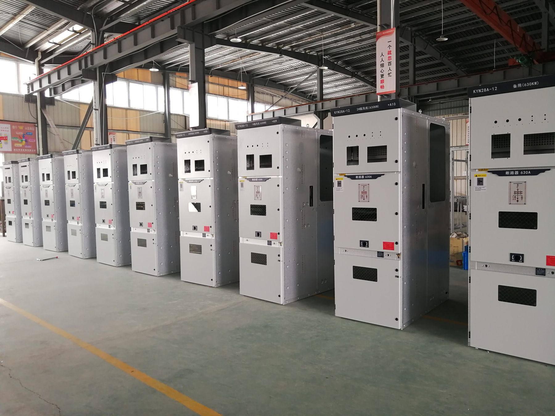
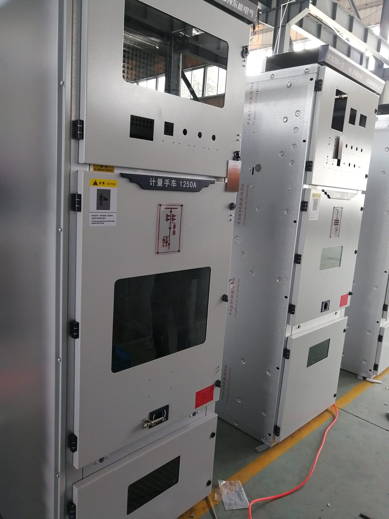
In a metal-clad cabinet the protection chain crosses three compartments, and each crossing is a place where wiring can be wrong. The CTs are in the cable or busbar compartment, mounted on the primary conductors. The relay is in the low-voltage compartment, behind the front door. The trip coil is inside the breaker truck, connected through a plug and socket that separates when the truck is racked out.
| Location | Equipment | Detail that decides whether it works |
|---|---|---|
| Cable compartment | Phase CTs, core-balance CT, earth switch | Polarity marks, secondary cable routing, single-point earthing of the secondary |
| Breaker truck | Vacuum interrupter, trip coil, auxiliary contacts | Trip coil voltage and burden, auxiliary contact changeover at the right travel position |
| Low-voltage compartment | Relay, test block, MCBs, trip circuit supervision relay | Test block that isolates without opening the CT circuit, DC MCB rating and discrimination |
Two details in that table are worth more attention than they usually get. The first is the test block. It has to allow the relay to be tested without opening the CT secondary circuit, because an open CT secondary develops a dangerous voltage across the open terminals. A test block that only disconnects the relay and leaves the CT loop open is worse than no test block at all.
The second is the auxiliary contact that carries the trip. It must be closed when the truck is in the service position and must change state only after the breaker has interrupted, not while the mechanism is still travelling. A contact that opens early interrupts the trip coil current before the breaker has cleared, and the breaker either fails to open or opens without the mechanism completing its sequence.
The DC Supply Is Part of the Protection System
A protection scheme is only as available as the battery behind it. The trip coil draws a pulse of several amperes at 110 V or 220 V DC, the relay and its indicating lamps draw a steady trickle, and both come from the same station battery through the same DC distribution board. When the battery is weak, the scheme does not fail at the relay: it fails at the coil, and it fails at exactly the moment the fault current is also depressing the battery voltage.
Three provisions follow from that. The trip circuit has to be supervised continuously rather than checked annually, and the supervision must work with the breaker both open and closed. The DC supply to each cabinet should be protected by its own MCB so that a fault in one panel does not remove the tripping supply from a whole switchboard. And the trip coil itself should be a monitored load, so that a coil that has already burnt out is discovered before the next fault rather than during it.
A breaker failure scheme belongs in the same discussion. If the local breaker does not open within its expected time, something upstream has to clear the fault, and that requires a timer started by the trip command and a signal to the upstream device. In a small installation this is often omitted, and the omission is only discovered when a breaker sticks.
Grading: The Study That Makes the Ratings Meaningful
Grading, or coordination, is the calculation that decides which device trips first for every possible fault location. It uses the actual time-current curves of the devices in series, from the service entry down to the smallest final circuit, and it produces a set of time intervals that must all be positive.
A margin of 0.3 to 0.4 seconds between the downstream and upstream operating times is the usual starting point. That margin has to absorb the breaker opening time, the overshoot of the upstream relay, its reset time if it is electromechanical, and the tolerance of both devices at the current in question. Where a transformer is between the two devices, the through-fault current and the transformer impedance change the picture, and the margin is usually increased.
Coordination also has a limit: at very high fault currents the time-current curves converge, and no amount of setting adjustment will keep the margin. That is the point at which the design moves the problem elsewhere, for example by adding a current-limiting device or by accepting that the upstream device will also operate and treating the resulting outage as acceptable. Knowing where that limit is, before the equipment is ordered, is the difference between a scheme that grades and one that is merely drawn.
CT Selection for Protection: Ratio, Class and Burden Together
The CT has to satisfy three requirements at once and they pull in different directions. The ratio has to produce a measurable secondary current at the smallest fault to be detected, and not an absurd one at the largest. The accuracy limit factor has to keep the CT out of saturation at the maximum through-fault current. The burden has to be inside the rated VA of the CT at that same current.
A 5P10 CT promises 10 times rated current within a composite error of 5 percent, but only into its rated burden. Add a long secondary run in 2.5 mm² cable and the actual burden rises; the same CT then saturates at a lower primary current and the accuracy limit factor in the datasheet no longer describes the installation. This is why protection CTs on long cable runs are routinely specified as 5P20, and why the calculation should be done rather than assumed.
The secondary current choice, 1 A or 5 A, follows the same logic from the other end. A 5 A secondary delivers more power into a short cable run and suits compact panels; a 1 A secondary keeps the VA burden low over long runs but quadruples the turns and the open-circuit voltage risk. The current transformer basics guide covers the ratio rules, and the ratio selection guide takes the worked example further.
Commissioning Checks That Catch the Wiring Errors
Most protection failures in the first year are wiring errors rather than equipment faults, and almost all of them are caught by four tests that take an afternoon.
- Secondary injection. Current is injected into the relay through the test block at each stage setting to confirm the pickup and the time delay. It proves the relay and its settings, not the CT or the primary wiring.
- Primary injection. Current is passed through the primary conductor to prove the whole loop: CT ratio, polarity, secondary wiring and relay reading together. This is the test that finds a reversed CT or a crossed phase.
- Trip test from the relay. The relay is operated and the breaker is confirmed to open, with the correct target indicated, proving the trip circuit, the auxiliary contact and the coil in one step.
- Trip circuit supervision test. The circuit is broken at the coil and the alarm is confirmed, without the breaker operating. This is the only way to know the supervision is actually connected.
Record the results against the settings sheet and keep them with the panel. When a breaker later operates unexpectedly, the commissioning record is what distinguishes a setting error from a genuine fault.
What to Specify in a Protection and Switchgear Package
A specification that names the relay model and stops there leaves the integration to the supplier. The following five items move the decisions back to the buyer, where they belong, and they fit on a single page.
- Fault level and earthing system. The maximum and minimum fault current at the busbar decide both the CT accuracy limit factor and the sensitivity of the earth fault element.
- CT ratios, classes and burden. Given per core, with the intended duty named: protection, metering or both.
- Protection functions required. Listed by ANSI code, including the ones that are not overcurrent: breaker failure, trip circuit supervision, under-voltage, and any interlocking.
- Test facilities. Type of test block, whether primary injection is possible without dismantling, and the position of the test terminals in the compartment.
- DC system. Voltage, battery autonomy, whether each cabinet has its own MCB, and the trip coil supervision arrangement.
The answers to those five questions also determine the price, which is why they are sometimes left vague until after the order. A cabinet with 5P20 CTs, a core-balance earth fault CT, full trip circuit supervision and a breaker failure relay is a materially different product from one with 5P10 CTs and a single overcurrent relay, and the difference is visible in the first fault.
Where Nahu Group Fits
Nahu Group supplies the equipment on both sides of that chain for 12 kV and 40.5 kV networks: metal-enclosed and armoured switchgear, vacuum circuit breakers, and the current transformers that feed the protection. Because the CTs and the cabinets come from the same factory, the ratio, class and burden can be checked against the relay they will actually drive rather than against a generic catalogue figure.
The useful input from a buyer is the single-line diagram with fault levels, CT ratios and the expected grading margin written on it. From that, the distribution cabinet range can be configured with the protection accommodation the scheme needs, the vacuum circuit breaker range matched to the breaking duty, and the current transformer range selected for the class the relays require.
Protection is bought for the day it operates. Everything above is a way of making sure that when that day comes, the signal that started at the busbar arrives at the trip coil intact.
Frequently Asked Questions About Protection and Switchgear
What is the difference between 50 and 51 in a protection scheme?
ANSI 50 is the instantaneous overcurrent element, set above the maximum fault current the downstream equipment can deliver, and it trips with no intentional delay. ANSI 51 is the time-delayed overcurrent element, with a definite or inverse time curve, which provides backup and covers faults beyond the reach of the instantaneous setting.
Why does a switchgear cabinet need three separate overcurrent stages?
Because one setting cannot be fast for a close-in fault and slow enough to grade with the device downstream. The instantaneous stage clears heavy faults at the busbar in milliseconds, the time-delayed stage covers the feeder along its length and provides backup, and the zero-sequence stage detects earth faults whose current is too small to move the phase elements.
What CT class should be used for overcurrent protection?
For overcurrent and earth-fault protection, a protection class CT such as 5P10 or 5P20 is normal, where the number after P is the accuracy limit factor and states how many times rated current the CT will still transform within its composite error. For differential or other schemes where the waveform itself is used, a class PX or TPS CT with a defined knee point is required instead.
Can a 5 A CT secondary be replaced by a 1 A secondary in the same cabinet?
Only as a matched set. The relay, the test block and the wiring are all built around the secondary current, and a 1 A relay on a 5 A CT will read one fifth of the true current. Replacing a CT with a different secondary rating means replacing or re-ranging every device in that circuit and re-checking the VA burden of the whole loop.
What is trip circuit supervision and why is it tested at commissioning?
It is a continuous check, usually ANSI 74, that proves the trip coil and its wiring are intact while the breaker is closed. Without it, a broken auxiliary contact or a blown DC fuse leaves a breaker that looks healthy and cannot trip. It is tested by simulating the open circuit at the coil and confirming the alarm appears without operating the breaker.
How much grading margin should be left between two overcurrent relays?
A margin of 0.3 to 0.4 seconds between the operating time of the downstream device and the upstream device is the usual starting point, and it must cover the breaker opening time, the reset time of the upstream element and the relay tolerances. Where the upstream device is an electromechanical relay or the CTs are close to saturation, the margin has to be larger.
Published November 3, 2026 · Nahu Group (NAHU Electric Technology)