
A neutral current transformer is a current transformer installed in the connection between a power transformer's neutral point and earth, so that it measures only the current that flows when an earth fault or a zero-sequence condition drives current through that connection. Its secondary winding feeds an earth-fault protection relay, an earth-leakage monitor or an unbalanced-load measurement. Because the neutral connection carries no current while the system is healthy and balanced, the device can be set to detect earth-fault currents that are a tiny fraction of the circuit rating, because there is no load current to mask them.
That single sentence is the whole point of the device, and it drives every sizing decision that follows. This guide covers what the neutral / earth-fault application requires, where the transformer is mounted in a 10–35 kV installation, how it differs from a core balance and a residual current transformer, and which parameters you have to fix before a supplier can quote. It is written for protection and substation engineers, utility specifiers and EPC contractors, and it stays deliberately on the earth-fault and unbalanced-monitoring application rather than repeating general current transformer theory.
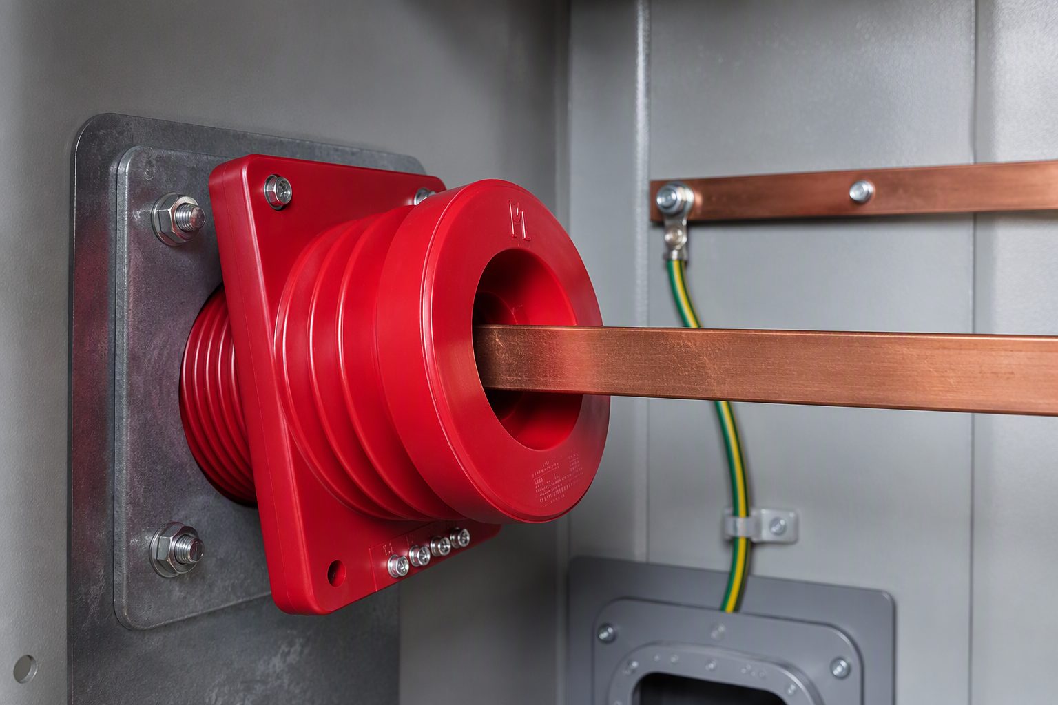
What Does a Neutral Current Transformer Do?
The device produces a scaled replica of the current in a conductor that is supposed to carry nothing in normal service. Two things follow from that:
- It measures residual current, not load current. The primary is the neutral-to-earth connection itself — a neutral link, a bar, or the earthing conductor of a generator or transformer winding. Phase load current never passes through it, so its whole measuring range can be spent on the small currents that matter.
- It defines what the protection can see. Everything downstream — relay setting, sensitivity, grading with other earth-fault elements — is limited by the ratio, the core behaviour at very low exciting current, and the burden the transformer has to drive.
The device does two jobs in practice. The first is earth-fault detection: restricted earth fault protection on a transformer winding, standby earth fault protection on a transformer neutral, or sensitive earth-fault protection where the fault current is deliberately limited by the system earthing method. The second is monitoring: on a four-wire system, the neutral connection carries the standing imbalance of the load, so the same signal can feed an ammeter, a transducer or an alarm function that reports sustained unbalance.
If you need the general theory of ratios, classes and construction, the current transformer basics page covers it. This page assumes that grounding and concentrates on the neutral application.
Where Is It Installed in a 10–35 kV Network?
There are three positions where a residual current measurement of this kind appears on a medium-voltage installation, and it is important to be clear about which one a project specification is asking for.
- In the transformer neutral. The transformer is mounted on the neutral link between the star point and the earthing electrode, usually inside the neutral or earthing cubicle. Where a neutral earthing resistor (NER) or reactor is fitted, the transformer goes on the transformer side of it, so the full earth-fault current passes through the primary and the impedance is inside the protected zone.
- In the generator or earthing-transformer neutral. The same arrangement appears in a generator neutral cubicle and on the neutral of an earthing transformer, where the primary current is the earth-fault current of the whole system section.
- Around the feeder cable rather than in a neutral. On a metalclad switchgear panel feeding a cable, there is often no neutral to install into, so the residual measurement is taken with a ring-shaped transformer placed around the cable cores close to the cable gland. That device is the core balance CT, and although the application is the same, the physical device is not.
Two installation details cause more commissioning problems than any other. The first is polarity: the CT's primary marking has to match the star-point convention used by the protection scheme, because the neutral measurement is compared against the phase measurements in restricted earth fault and differential functions, and a reversed connection can make a secure scheme inoperative or an insecure one operate. The second is secondary earthing: the secondary circuit of a current transformer is earthed at one point only, and a neutral transformer's secondary wiring shares a cable route with the trip circuits, so the earthing arrangement belongs in the drawing package rather than in the field.
For the switchgear-mounted case, the cable compartment geometry, the gland plate and the number of cores per phase all constrain the device. That is why a procured medium-voltage current transformer and its residual counterpart are usually specified together, as a single protection package, rather than ordered separately from different documents.
Neutral Current Transformer vs Core Balance CT vs Residual CT: Which Do You Need?
The three names are used almost interchangeably in tender documents, and they are not the same device. Choosing the wrong one changes the sensitivity you can achieve, the cable-compartment space you need, and the wiring you have to run to the relay.
| Neutral current transformer | Core balance CT | Residual (summation) CT | |
|---|---|---|---|
| What the primary current is | The current in a neutral or earthing connection between a star point and earth | The vector sum of the phase currents passing through the window, plus any neutral core that is routed through it | The arithmetic sum of the secondary outputs of three separate phase current transformers |
| Physical form | Bar-primary, wound or window type, mounted in a neutral link or earthing cubicle | Ring or toroid around the cable cores, close to the cable gland; split-core versions exist for cables that are already terminated | Three ordinary phase current transformers and a summation connection in the relay or in an interposing unit |
| What limits the usable sensitivity | Excitation current of a single core at very low primary current, and the ratio you select | Excitation current of a single core, the position of the cable inside the window, and stray flux from earthed metalwork | Excitation currents of three cores adding together, plus unequal burden and unequal phase errors |
| Typical protection function | Restricted earth fault, standby earth fault, transformer and generator neutral earth fault, neutral current alarm | Sensitive earth fault and directional earth fault on cable feeders | Standard earth-fault (residual) element on a feeder where no ring core is fitted |
| Where it is mounted | Neutral or earthing cubicle, on the transformer side of any earthing resistor or reactor | Cable compartment of the switchgear, around the cable cores at the gland plate | On the phase conductors inside the switchgear or in the protection panel |
| What to watch during installation | Primary polarity relative to the star point, one-point secondary earthing, shorting links for maintenance | Every core of every phase passing once and in the same direction, an unobstructed window, correct handling of cable screens and armour | Matched ratio, class and burden on all three phase cores, because their errors appear directly in the residual signal |
The reason a dedicated core beats a summation connection for sensitive work is documented in the Network Protection & Automation Guide, which puts the saving at roughly three to one: using one core instead of three residually connected ones cuts the magnetising current at relay operation in that proportion. That reduction is what makes low settings practicable, and it also explains why the secondary turns of a core balance device need not be tied to the cable rating — with no secondary current under balanced conditions, the turns can be chosen to optimise the effective primary pick-up.
How Do You Size a Neutral Current Transformer?
Sizing a neutral CT starts from a different premise from phase current transformer selection. There is no continuous load current in the primary, so the rating question is not "what is the circuit current" but "what is the smallest earth-fault current the protection must detect, and what is the largest current the transformer must survive". Work through the four steps below in order.
Step 1 — Establish the earth-fault current range for the point of measurement
Get both ends of the range from the network study. The minimum value comes from the system earthing method: a solidly earthed network can produce a large earth-fault current, while a resistance-earthed or compensated network limits it deliberately, and in a compensated network the residual current becomes small and is strongly influenced by the tuning of the arc-suppression coil. The maximum value sets the thermal duty. A CIRED study of sensitive directional earth-fault protection in compensated medium-voltage networks shows that the measurement errors of the residual current device have a direct effect on whether the protection operates correctly.
Step 2 — Choose the ratio from the sensitivity you need, then check the relay
Select the ratio so that the smallest earth-fault current you have to detect produces a secondary current well above the relay minimum setting, with margin for the measuring error discussed next. Then check the other direction: the relay's setting range has to cover your target, and its burden has to be within what the transformer can drive at that current without the error growing unacceptable. If the two ends cannot both be satisfied, the answer is usually an interposing transformer or a different relay, not a compromise on primary sensitivity.
Step 3 — Confirm what the accuracy class actually promises
This is the step that decides whether sensitive earth-fault protection works. A protection class such as 5P is defined at a specified operating point rather than as a curve across the whole primary current range, and the 2017 CIRED paper on core balance transformer errors makes the point directly: for a class-defined device the error is only stated at one operating condition, so the error at the small residual current used for sensitive earth-fault protection has to be assessed separately. Ask the supplier for the error at the current the relay will actually see, and confirm the edition of the applicable standard that figure is stated against — the current transformer requirements sit in IEC 61869-2 and the general instrument transformer requirements in IEC 61869-1, both listed under Sources below.
Step 4 — Check thermal rating, insulation level, window and burden together
- Thermal. The neutral CT must have a defined short-time thermal current rating that covers the earth-fault current for the duration the protection takes to clear it. The National Grid specification listed under Sources, for example, requires that this rating is not less than the corresponding rating of the associated switchgear or primary plant. The exact rating and test definitions must be taken from the current edition of the applicable standard.
- Insulation. The rated insulation level has to match the system it is installed in and, for a neutral device, the insulation stress it actually sees, which differs from a phase current transformer's.
- Window and position. For a ring-type device, the window has to accept every core that must be enclosed with room to spare, and the position has to keep the cable or bar central. Cable screens and armour taken through the window change the measurement, so fix the screen earthing arrangement before ordering.
- Burden. Add the relay burden and the lead burden, choose the secondary current (lead burden falls with the square of the secondary current, so a 1 A secondary keeps the lead burden lower than a 5 A secondary over the same cable run), and state the burden in the specification. A device ordered without a stated burden is a device whose error cannot be checked.
- Retrofit or new build. On existing switchgear, a split-core device allows the residual measurement to be added without dismantling the cable termination, which is usually the deciding factor in a station that cannot be taken out of service; the trade-offs are set out in the guide to current transformers for new installations and retrofitting.
Unbalanced-Load Monitoring: What the Neutral Connection Can and Cannot Tell You
In a four-wire system the neutral conductor carries the imbalance of the three phase currents, so a neutral CT is a direct unbalance sensor: a transducer or relay connected to it can report standing neutral current, log a trend, or raise an alarm before the imbalance grows into an overload on one phase. That is a genuinely useful function in a distribution substation, and it needs no additional calculation.
Two limits are worth stating clearly, because they are frequently misunderstood in tenders:
- In a three-wire medium-voltage circuit there is nothing for the unbalance to return through. The three line currents sum to zero at every instant, so load unbalance on its own produces no current in a neutral connection or in the window of a ring-type device — only a current with a path through earth does. A residual device in that network is a protection device, not an unbalance meter.
- The setting has to clear the standing residual current. Where an unbalance current does flow in normal service, the protection setting must sit above it and the grading must be verified against it. A protection element set below the normal standing residual current will operate on load conditions rather than on faults, and no amount of testing afterwards will fix a setting chosen without the measured standing value.
What Should You Ask a Supplier For?
A neutral CT is a small item with a disproportionate effect on protection performance, so the questions that matter are the ones that let you verify performance rather than the ones that let you compare prices.
- Type test and routine test documentation referring to a named IEC standard edition, with the configuration described, rather than a general statement of compliance.
- The full rating set on the datasheet: ratio and rating factor, rated continuous thermal current, short-time thermal current and its duration, rated burden with the power factor, accuracy class, insulation level, and the primary and secondary construction.
- The error statement at the low primary current the protection will use, not only the class designation — this is the single most useful figure for an earth-fault application.
- Mechanical data: window dimensions, mounting arrangement, terminal type for shorting and earthing links, and the sealed overall dimensions, so the device can be checked against the cubicle drawing before delivery.
- Polarity and terminal marking convention, stated explicitly on the drawing, and the recommended secondary earthing point for the scheme.
Nahu Group manufactures current transformers, voltage transformers, metering boxes and medium-voltage switchgear for 10–35 kV distribution networks, including residual and neutral-type current transformers for earth-fault protection and neutral current measurement, . What a buyer should require in every case is the project-specific evidence for the equipment ordered — the standard edition, the tested configuration and the ratings — confirmed against the applicable standard for the destination network.
Five Specification Mistakes That Reappear on Every Project
- Specifying a class but not the error at the operating current. The class is a reference point. The earth-fault setting lives far below it, and that is where the measurement has to be good enough.
- Sizing the ratio from the load current. The primary carries no load current, so a ratio copied from the phase current transformer wastes the whole advantage of the device.
- Forgetting the earthing resistor in the zone. A neutral device mounted on the electrode side of the NER leaves the impedance outside the measurement and defeats the protection function.
- Leaving screens and armour to the installer. Whether a cable screen passes through the window changes the measurement, so the decision belongs in the design.
- Omitting the burden. Without a stated relay and lead burden, the accuracy figure has no defined meaning, and the completed circuit may not meet the setting that was calculated.
Frequently Asked Questions
What is a neutral current transformer used for?
It is used to measure the current flowing in the neutral-to-earth connection of a transformer, generator or earthing device, so that a protection relay or monitoring device can detect earth faults and earth leakage. The same secondary signal is used to monitor the standing neutral current produced by unbalanced loading.
Where is a neutral current transformer installed on a transformer?
In series with the neutral connection between the transformer star point and the earthing electrode, normally inside the neutral or earthing cubicle. Where a neutral earthing resistor or reactor is used, the transformer is fitted on the transformer side of that device so that the full earth-fault current passes through its primary.
Is a core balance CT the same as a neutral CT?
They are both used to obtain a residual current signal, which is why the names get mixed up, but they sit in different places. A neutral current transformer measures the current in a neutral conductor or neutral link. A core balance CT is a ring-shaped transformer that surrounds the phase conductors, so it measures the vector sum of the phase currents without any connection into the current-carrying circuit.
What ratio should a neutral current transformer have?
The ratio is chosen from the smallest earth-fault current that has to be detected rather than from the load current, because no load current flows in the primary under healthy conditions. Pick a ratio that keeps the secondary current comfortably above the relay minimum setting, then confirm the relay setting range, the connected burden and the thermal rating of the transformer.
Can the residual connection of three phase CTs replace a neutral CT?
Sometimes, but with a loss of sensitivity. Three residually connected phase cores add their excitation currents together, so the residual signal carries about three times the magnetising current of a single core. Where the earth-fault current to be detected is small, a dedicated neutral or core balance transformer gives the better signal-to-noise ratio.
Why does a neutral CT need an accuracy check at low current?
A protection class such as 5P defines its error limits at one specified operating point, not across the whole range, so the error at a small residual current can be much larger than the class number suggests. Published CIRED work on sensitive earth-fault protection shows that the measurement errors of a core balance transformer at low residual current have a direct effect on whether the protection operates correctly, which is why the error should be assessed at the current the relay will actually see.
Should the neutral CT be mounted above or below the earthing resistor?
Between the transformer neutral and the earthing resistor or reactor, so that the whole earth-fault current passes through its primary. If it is fitted on the electrode side of the resistor, the resistance sits outside the measured circuit and the protection no longer supervises the current path it was installed to watch.
Sources and Further Reading
- IEC 61869-2:2012 — Additional requirements for current transformers — the product standard for newly manufactured inductive current transformers used with measuring instruments and protective devices, and the source of the standard rated secondary values
- IEC 61869-1:2023 — Instrument transformers, general requirements — the product-family general requirements that sit above the current transformer part
- CIRED 2017: Effect of core balance current transformer errors on sensitive earth-fault protection — how the measuring errors of a core balance transformer affect residual-current and neutral-admittance earth-fault protection, and how to select a device for that duty
- Electrical Engineering Portal — using a core-balance current transformer for earth fault protection — ring-type construction, mounting at the cable gland, split-core versions for existing switchgear, and the reduction in magnetising current compared with three residually connected cores, after the Network Protection & Automation Guide
- National Grid Technical Specification TS 3.02.04 (RES), Current Transformers for Protection and General Use — a worked example of how a transmission operator writes current transformer requirements: IEC 61869-1 and IEC 61869-2 compliance, terminal and rating-plate marking, selection of the rated continuous primary current from the standard values, and a short-time thermal current rating not less than the associated primary plant
A neutral current transformer is best specified backwards. Start from the earth-fault current the protection has to detect at the point of measurement, decide whether the device will sit in a neutral connection or around the cable, then fix the ratio, the error at the operating current, the burden and the thermal duty. The device is inexpensive relative to the plant it protects, but the protection function it enables is only as good as the measurement it delivers, and the measurement is decided entirely in the specification stage.
Nahu Group supplies current transformers, voltage transformers and metering equipment for 10–35 kV networks, including residual-type current transformers for earth-fault protection and neutral current measurement, and can advise on the configuration that fits a given cubicle and relay. See the current transformer range, or send the engineering team the system voltage, earthing method and relay type for your project.
Published September 21, 2026 · Nahu Group (NAHU Electric Technology)