
A current transformer is a measurement transformer that steps a high primary current down to a small, proportional secondary current, so that meters, relays, monitoring systems and protection equipment can read the current in a circuit without being exposed to it directly. Instead of forcing dangerous or impractical current levels into instruments, a current transformer produces a scaled-down copy of the current flowing in the primary conductor. If you work in electrical engineering, panel building, utility metering or industrial power distribution, understanding CT technology makes it much easier to choose the right gear and avoid expensive mistakes.
What is a current transformer?
A current transformer, often shortened to CT, is an electrical transformer designed specifically to measure alternating current. It takes a high primary current from a conductor or busbar and produces a smaller secondary current that is proportional to the original current. That smaller current can then be sent to meters, energy monitoring devices, protective relays or control equipment.
The key idea is simple: the CT does not usually power a load like a regular electrical transformer. Its job is measurement and protection. It gives the system a scaled-down copy of the current flowing in a circuit, so engineers and operators can see what is happening without putting sensitive equipment directly in the high-current path.
For example, a feeder may carry hundreds or thousands of amps. A meter cannot safely handle that current directly. A current transformer makes that current readable by converting it into a standard secondary signal, commonly used for metering or relay inputs depending on the system design.
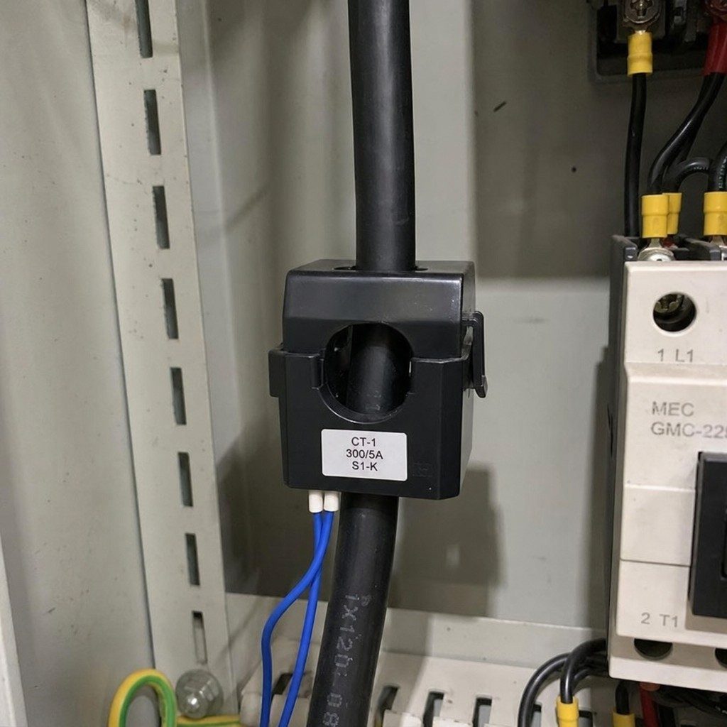
Why does CT technology matter in real power systems?
CT technology matters because modern electrical systems need accurate current data to stay safe, efficient and predictable. Without current transformers, it would be much harder to measure large currents, detect faults, bill energy use, protect equipment or monitor load behaviour in real time.
In everyday terms, a CT is like a trusted translator between the power circuit and the control system. The power circuit may be dealing with high current and medium voltage. The metering or protection device needs a much smaller, safer signal. The current transformer sits between them and makes that conversation possible.
This is why CTs show up almost everywhere in serious power infrastructure, including:
- Utility substations and distribution networks
- Industrial switchgear and control panels
- Medium-voltage metering cabinets
- Renewable energy systems
- Motor control centres
- Building energy monitoring systems
- Protection relay schemes
- Power quality and load analysis systems
For buyers, the practical benefit is clear. The right CT helps your system measure current accurately, respond to abnormal conditions and support safer electrical operation. The wrong CT can create bad readings, nuisance trips, poor billing data or protection gaps.
How does a current transformer work?
A current transformer works through electromagnetic induction. The primary current flowing through a conductor creates a magnetic field, and that magnetic field induces a current in the CT's secondary winding. The secondary current follows a known ratio, so the connected meter or relay can interpret it as the real current flowing in the primary circuit.
In many CT designs the primary "winding" is not a coil at all. It may simply be the cable or busbar passing through the CT window. That is why a donut current transformer, also called a ring-type or toroidal CT, can be placed around a conductor and still perform the same basic function.
The ratio is the heart of CT selection
Every current transformer has a current ratio. A ratio tells you how the primary current relates to the secondary current. For example, a CT ratio may indicate that a large current on the primary side is represented by a much smaller current on the secondary side.
This ratio needs to match the expected operating current of the circuit. If the ratio is too low, the CT may saturate or fail to provide useful readings under heavy load. If the ratio is too high, the meter may lose resolution at normal operating current. Good selection is not about picking the biggest CT you can find; it is about choosing one that fits the real load profile. For a step-by-step method, see how to choose the right current transformer ratio.
The secondary circuit must be treated with respect
One of the most important safety rules in electrical engineering is this: never open-circuit the secondary of an energised current transformer unless the system is designed and handled safely. An open secondary can create dangerous voltage because the CT is trying to maintain current flow in the secondary circuit.
That is why CT wiring, shorting blocks, terminal polarity, burden and grounding practices matter. Even though a CT is a measurement device, it is still connected to a power system. Treat it like professional electrical equipment, not a casual accessory.
Accuracy depends on the whole setup
CT accuracy is not only about the transformer itself. The connected meter, wiring length, burden, frequency, operating current range and installation quality all affect performance. A high-quality CT can still deliver poor results if it is installed incorrectly or paired with the wrong secondary load.
When you are buying a current transformer, do not only ask, "What is the ratio?" Also ask about accuracy class, rated burden, insulation level, application environment and whether the product is designed for metering, protection or both.
The main transformer types used for current measurement
There are several transformer types in the CT world, and each one exists because different installations have different priorities. Some are built for new switchgear. Others are ideal for retrofits. Some focus on precision metering, while others are built to support protection systems during fault conditions.
Donut current transformer
A donut current transformer has a circular or window-style core with an opening in the centre. The conductor passes through the opening, and the CT measures the magnetic field created by the current in that conductor. This design is popular because it is simple, compact and clean.
A donut current transformer is commonly used where the conductor can be routed through the CT during installation. It is a great fit for many panels, metering setups and monitoring systems. Because the core is continuous, it can also provide strong measurement performance when properly specified.
The main limitation is installation access. If the cable or busbar is already in place and cannot be disconnected or threaded through the opening, a solid ring-type CT may not be convenient. In those cases, a split-core design may be easier.
Solid core current transformer
A solid core current transformer uses an unbroken magnetic core. This design often provides better accuracy and stability than a split-core option because there is no opening joint in the core path. For new installations, where conductors can be passed through the CT before final termination, solid core CTs are a dependable choice.
The trade-off is flexibility. Once the electrical system is already built, installing a solid core current transformer may require disconnecting conductors or planning around busbar access. For OEM panels, switchgear manufacturing and controlled new-build projects, that is usually not a problem. For live retrofit work, it may be a bigger headache.
Split-core current transformer
A split-core CT opens and closes around an existing conductor. That makes it attractive for retrofits, energy audits and upgrades where shutting down equipment or disconnecting cables is difficult. If you are adding monitoring to an existing facility, this style can save time. Our split-core current transformer guide covers retrofit practice in more detail.
The convenience comes with a few things to watch. The core must close properly, the mating surfaces must stay clean, and the CT needs to be selected carefully for the application. For precision work, always check whether the accuracy class and burden match your metering requirements.
Bar-type and wound-primary CTs
A bar-type CT includes a built-in primary conductor, usually designed for switchgear or busbar applications. This provides a robust structure for higher-current installations and can simplify integration into engineered equipment.
A wound-primary CT has primary turns built into the transformer. This can be useful for lower-current applications where more primary turns help create a stronger magnetic signal. These designs are less about quick retrofitting and more about engineered performance in specific equipment layouts.
Medium-voltage cast-resin CTs
In medium-voltage environments, CTs often need more than a compact shape. They need insulation performance, mechanical strength and environmental durability. Cast-resin current transformers are commonly used in switchgear, substations and metering equipment because the epoxy body helps support insulation and protection for demanding installations.
This is the kind of area where working with a dedicated manufacturer really pays off. Product selection has to consider voltage level, mounting style, accuracy class, rated current, secondary windings, insulation requirements and the standards required for the project. The medium-voltage current transformer specification guide walks through the same variables in a specification checklist.
| How it is built | How it is installed | Where it fits best | |
|---|---|---|---|
| Donut (ring / toroidal) | Circular window-style core with an opening in the centre | The conductor or busbar is threaded through the window | Panels, metering setups and monitoring systems where the conductor can be routed through the CT |
| Solid core | Unbroken magnetic core with no joint in the core path | The conductor is passed through before final termination | New switchgear, OEM panels and controlled new-build projects where accuracy and stability matter most |
| Split-core | Core that opens and closes around a conductor | Clamped around a conductor already in place | Retrofits, energy audits and upgrades where shutdown or disconnection is difficult |
| Bar-type | Built-in primary conductor for switchgear and busbar use | Bolted into engineered equipment | Higher-current switchgear and busbar installations |
| Wound-primary | Primary turns built into the transformer | Fixed engineered layout | Lower-current applications where more primary turns create a stronger magnetic signal |
| Medium-voltage cast-resin | Epoxy / cast-resin body providing insulation and mechanical strength | Fixed engineered installation in medium-voltage equipment | Switchgear, substations and medium-voltage metering equipment in demanding environments |
How do you choose the right current transformer for your application?
Choosing the right current transformer means matching the CT to the current level, voltage environment, accuracy needs, installation method and connected equipment. In plain language, you want a CT that reads accurately during normal operation, stays reliable under system stress, and physically fits the way your project is built.
Start with the job the CT needs to do. Is it for revenue-grade metering, general monitoring, protection, load control, or a complete medium-voltage metering cabinet? A protection CT and a metering CT may look similar from the outside, but they are not selected the same way.
Use this checklist before buying:
- Define the primary current range. Know the normal load, expected peak load and possible fault conditions.
- Select the correct CT ratio. Choose a ratio that gives useful readings during normal operation without overloading the CT.
- Confirm the system voltage. Low-voltage panel CTs and medium-voltage switchgear CTs are very different products.
- Check the accuracy class. Metering, monitoring and protection applications may require different accuracy behaviour.
- Review the rated burden. The CT must support the connected meter, relay, wiring and terminals without losing accuracy.
- Match the physical design. Decide whether you need a donut current transformer, solid core current transformer, split-core CT, bar-type CT or cast-resin unit.
- Plan the installation. Think about cable size, busbar dimensions, mounting space, polarity markings and access for maintenance.
- Ask for technical data. Good suppliers should provide drawings, ratings and product details so your engineering team can verify the fit.
If you are not sure which model fits, do not guess. Send your circuit data, installation layout and metering or protection requirements to a specialist supplier. A quick technical review upfront is much cheaper than replacing mismatched equipment later.
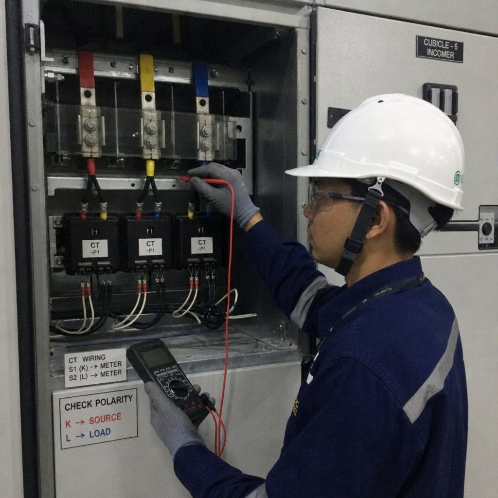
Common installation mistakes to avoid
Most CT problems are not dramatic at first. They show up as strange meter readings, phase mismatches, inconsistent energy data, or relay behaviour that does not make sense. The good news is that many of these issues come from avoidable installation mistakes.
Watch out for these common problems:
- Wrong polarity. CTs have polarity markings, and reversing them can create incorrect readings or protection logic errors.
- Incorrect phase matching. A CT on phase A must match the voltage reference and meter input for phase A.
- Open secondary circuit. This can be dangerous on an energised CT and should be prevented with correct wiring and shorting practices.
- Excessive burden. Long wiring runs or mismatched devices can push the CT beyond its rated burden.
- Poor conductor positioning. In window-type CTs, the conductor should be routed as intended by the manufacturer.
- Using the wrong CT type. A convenient retrofit CT may not be the best option for precision metering or medium-voltage equipment.
- Ignoring the environment. Heat, moisture, dust, vibration, and indoor versus outdoor use all affect product choice.
A clean installation does more than make the panel look professional. It protects the accuracy of the measurement and helps the whole power system behave the way the design intended.
How are current transformers and electrical transformer basics connected?
A current transformer is part of the broader electrical transformer family, but its purpose is specialised. A power transformer transfers energy between circuits to change voltage levels. A current transformer transforms current for measurement, monitoring and protection. Our electrical transformer basics primer covers the wider family this device belongs to.
That difference is important for buyers. You are not just buying "a transformer." You are buying a measurement device that must stay accurate, insulated and dependable in a specific electrical environment. That is why CT datasheets include details like ratio, accuracy class, burden, rated insulation level, rated frequency, thermal current, dynamic current and installation type.
In practical electrical engineering, CTs are also tied closely to voltage transformers, metering boxes, switchgear, relays and control systems. A good metering setup is never just one component. It is a coordinated package where each part supports the others.
How NAHU Group supports CT projects
If you are sourcing current transformers for utility, industrial or medium-voltage metering projects, NAHU Group is worth a serious look. NAHU Group, also known as NAHU Electric Technology, manufactures current transformers, voltage transformers, metering boxes, vacuum circuit breakers, load break switches, fuses, lightning arresters, isolating and earthing switches, and cable accessories. Its website also highlights ISO 9001 certification, IEC 61869 type-tested products and current transformer models for 3–35 kV applications.
That matters because CT selection is often connected to a larger package. Maybe you need an indoor cast-resin CT for switchgear. Maybe you need a complete metering solution. Maybe your project needs technical drawings, accuracy details and support before a purchase order can move forward. A manufacturer with a focused product range can help you connect those dots faster.
For commercial buyers, the benefit is simple: fewer random parts, fewer unclear specifications, and a cleaner path from requirement to quote. Instead of trying to force a generic current transformer into a demanding application, you can start with the actual project conditions and work toward a better match.
Key takeaways before you buy
A current transformer is small compared with the equipment around it, but it plays a big role in safe and accurate power measurement. Choose it casually, and you may end up with unreliable data. Choose it properly, and it becomes a dependable part of your metering, monitoring or protection system.
Here is the quick version:
- A current transformer steps high current down to a usable secondary signal.
- CT technology supports metering, monitoring, protection and load analysis.
- Donut current transformer designs are compact and practical when conductors can pass through the CT window.
- Solid core current transformer designs are strong options for planned installations where accuracy and stability matter.
- Split-core CTs are useful for retrofits, but they still need careful selection.
- Ratio, accuracy class, burden, voltage level and installation style all matter.
- Medium-voltage CT projects should be handled with proper engineering review and supplier support.
If you are ready to choose a current transformer instead of just reading about one, head to nahugroup.com and explore NAHU Group's current transformer and metering equipment range. Send your project requirements, ask for the right model recommendation, and get a quote built around your actual application.
Frequently asked questions about current transformers
What is a current transformer used for?
A current transformer is used to measure alternating current. It takes a high primary current from a conductor or busbar and produces a smaller secondary current proportional to it, which is then sent to meters, energy monitoring devices, protective relays or control equipment. Its job is measurement and protection rather than powering a load.
What is a donut current transformer?
A donut current transformer, also called a ring-type or toroidal CT, has a circular window-style core with an opening in the centre. The conductor passes through that opening and the CT measures the magnetic field the current creates. The design is compact and simple, and because the core is continuous it can give strong measurement performance when correctly specified. Its main limitation is installation access: the conductor has to be threaded through the window.
What is the difference between a solid core and a split-core current transformer?
A solid core current transformer uses an unbroken magnetic core, so there is no opening joint in the core path. That usually gives better accuracy and stability, which suits new installations where conductors can be passed through before final termination. A split-core CT opens and closes around an existing conductor, so it can be fitted without disconnecting cables, which suits retrofits, energy audits and upgrades. The core must close properly and the mating surfaces must stay clean.
Why must the secondary circuit of a current transformer never be left open?
Never open-circuit the secondary of an energised current transformer unless the system is designed and handled safely. An open secondary can create a dangerous voltage because the CT is trying to maintain current flow in the secondary circuit. That is why CT wiring, shorting blocks, terminal polarity, burden and grounding practices matter, and why a CT should be treated as professional electrical equipment rather than a casual accessory.
How do you choose the right current transformer ratio?
Match the ratio to the expected operating current of the circuit. If the ratio is too low the CT may saturate or fail to give useful readings under heavy load; if it is too high the meter may lose resolution at normal operating current. Define the normal load, expected peak load and possible fault conditions first, then choose the CT that fits that real load profile rather than the largest one available.
What affects current transformer accuracy?
Accuracy is not only about the transformer itself. The connected meter, wiring length, burden, frequency, operating current range and installation quality all affect performance. A high-quality CT can still deliver poor results if it is installed incorrectly or paired with the wrong secondary load. When buying, ask about accuracy class, rated burden, insulation level and application environment, not only the ratio.
Can you install a current transformer on an existing cable without a shutdown?
In many cases yes, but only with a split-core design. A split-core CT opens and closes around an existing conductor, so it can be fitted where shutting down equipment or disconnecting cables is difficult. A solid ring-type or donut CT needs the conductor threaded through the window, so the cable or busbar must be accessible and disconnected. Choose the CT type around the installation method your site actually allows.
What should you check before buying a current transformer?
Confirm the primary current range including normal, peak and fault conditions; select the correct CT ratio; confirm the system voltage because low-voltage panel CTs and medium-voltage switchgear CTs are different products; check the accuracy class for metering, monitoring or protection; review the rated burden against the connected meter, relay, wiring and terminals; match the physical design to your installation; plan cable size, busbar dimensions, mounting space, polarity markings and maintenance access; and ask the supplier for drawings, ratings and product details so your engineering team can verify the fit.
Sources and further reading
- IEC 61869-2:2012 — Instrument transformers, Part 2: Additional requirements for current transformers — the IEC product standard for inductive current transformers used with measuring instruments and protective devices, rated 15 Hz to 100 Hz
- IEC 61869-1:2023 — Instrument transformers, Part 1: General requirements — the product family standard for instrument transformers above 1 kV AC, including error limits and type, routine and commissioning tests
- IEC TR 61869-100:2017 — Guidance for application of current transformers in power system protection — technical report on applying protective current transformers
Published September 21, 2026 · Nahu Group (NAHU Electric Technology)