
Every current transformer is defined by its ratio: the relationship between the current flowing in the primary conductor and the much smaller current delivered to the secondary terminals. A 600/5 A CT, for example, steps 600 A of primary current down to 5 A on the secondary, while a 600/1 A CT delivers 1 A instead. Choosing the right CT ratio is one of the most consequential decisions in a metering and protection design, because the same ratio must serve the meter at normal load and the relay under fault current. Pick it poorly and the meter reads outside its accurate range, the relay fails to pick up on time, or the core saturates early during a large fault.
In this guide, Nahu Group (NAHU Electric Technology) sets out a four-step method for selecting the current transformer ratio, explains the practical trade-off between 5 A and 1 A secondary outputs, and finishes with a worked example on a typical 400 A industrial feeder. Accuracy class selection — 0.2S versus 5P and the rest — is a related but separate subject, covered in the Choosing the Right CT Accuracy Class: 0.2S, 0.5S & 10P article, so this page stays focused on the ratio itself.
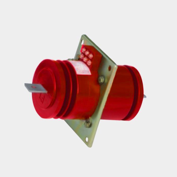
What is a current transformer ratio?
The current transformer ratio is the turns relationship written on the nameplate as primary current over secondary current, such as 200/5 A, 600/5 A, or 1000/1 A. The primary rating is the current the CT is designed to carry on its primary conductor at rated conditions, and the secondary rating is the standardized output fed to instruments. Because the secondary current is proportional to the primary current, a CT ratio of 600/5 A means that at exactly 600 A on the primary side, the ideal secondary output is 5 A; at 300 A it is 2.5 A, and at 60 A it is 0.5 A. Meters and relays then scale that secondary signal back to the real feeder current using the same ratio.
Why the CT ratio matters
Ratio selection matters for two reasons: metering accuracy and protection performance. A metering CT is most accurate when the feeder normally runs at a healthy fraction of the rated primary current, typically between 20% and 100% of rating. If a 400 A feeder is fitted with a 2000/5 A CT, the meter spends its working life at 20% of rating or below, where ordinary accuracy classes lose precision and energy data becomes unreliable. Special S-class metering cores such as 0.2S help at low currents, but they cannot rescue a badly oversized ratio.
Protection is the mirror image. Overcurrent relays set their pickup in terms of the CT ratio, and differential or earth-fault schemes depend on CTs at both ends of a protected zone matching correctly. A ratio chosen too small for the load can push the CT toward saturation during through-faults, distorting the secondary waveform precisely when the relay must discriminate. The goal, then, is a ratio that sits comfortably around the real load for the meter while still transforming fault current faithfully for the relay — which is why most feeders end up with a ratio a step or two above the full-load current.
Step 1: Determine the design current and future growth
Start with the feeder’s design or full-load current, taken from the load schedule, the transformer rating feeding the bus, or site measurements over a representative period. Add a margin for future growth so the CT does not need replacing the first time the plant expands. A practical target is to keep the expected operating current between roughly 30% and 100% of the rated primary current: high enough for metering accuracy, low enough to leave headroom for load growth and inrush events.
Step 2: Choose a standard primary rating above it
Next, move up to a standard primary rating that exceeds the design current with margin. Standard current transformer primary ratings follow the conventional series used across IEC-compliant equipment — values such as 100, 150, 200, 300, 400, 500, 600, 800, 1000, 1200, 1500, and 2000 A — so pick the next step above your design figure. If the full-load current is 380 A with planned growth, a 600 A primary is a safer choice than a 400 A primary that leaves almost no headroom. At the same time, confirm that the CT’s short-time thermal withstand covers the system fault current for the duration the protection takes to clear it.
Step 3: Pick the secondary: 5 A or 1 A
With the primary rating fixed, the ratio still has a second half to decide: whether the secondary output is 5 A or 1 A. Both are standard, and the right answer depends on wiring distance, burden, and the connected devices.
- 5 A secondaries are the traditional choice, compatible with most electromechanical and electronic meters and relays, and they make the most of the CT’s rated VA at the terminals.
- 1 A secondaries draw far less current through the pilot wiring, so the burden added by long cable runs falls dramatically. Where the CT sits in a switchboard and the relay lives in a remote control room tens or hundreds of meters away, 1 A often preserves accuracy that a 5 A circuit would lose to lead resistance.
- Modern electronic meters present a very small burden, which makes the 5 A versus 1 A choice less about the meter itself and more about the total secondary loop: CT terminals, wiring, terminals, test blocks, and device inputs.
A useful rule is to calculate the secondary loop resistance, multiply it by the secondary current you are considering, and confirm the resulting VA stays within the CT’s rated burden for the accuracy class. When in doubt, relay and meter manuals usually state the maximum lead resistance they support.
Step 4: Confirm metering and protection cores
The ratio is selected once for the feeder, but it is delivered separately to meters and relays through dedicated cores. A revenue metering core should carry a metering accuracy class that is accurate at low current, while a protection core carries a protection class with an accuracy limit factor so it keeps transforming during faults. Confirm both cores on the same CT share the ratio you selected, and verify the final ratio, class, and burden against the nameplate before installation — the guide to reading an instrument transformer nameplate shows exactly which markings to check.
Worked example: a 400 A feeder to 600/5 A
Consider a 400 A feeder supplying an industrial plant, with metering for energy billing and an overcurrent relay for protection. The design current is 400 A and the plant expects modest growth, so a standard 600 A primary is chosen: 400 A sits at 67% of rating, comfortably inside the accurate metering band with room to grow. The relay is mounted in the same switchboard room, the secondary wiring is short, and the connected burden is modest, so a 5 A secondary is preferred for compatibility with the installed relay and meter. The specification becomes a 600/5 A CT with two cores: a 0.2S metering core for the revenue meter and a 5P10 protection core for the relay, meaning the protection core holds its error within 5% up to ten times rated current. The relay’s pickup, typically set at 1.1 to 1.3 times the CT primary or a fixed secondary current such as 5 A, now maps cleanly onto the real feeder current.
If that same feeder were metered from a control room 150 m away, the engineering answer would likely change to a 600/1 A CT so the long pilot loop stays within burden, while the protection core could remain on the same ratio. The ratio is the easy part to keep identical; the secondary and the cores are where the design detail lives.
Ratio, class, and where Nahu fits in
Ratio and accuracy class go hand in hand, and choosing the class is where many projects stumble. Because this guide deliberately avoids repeating that material, follow the Choosing the Right CT Accuracy Class: 0.2S, 0.5S & 10P article once the ratio above is settled.
When a feeder load sits between the standard steps, custom ratios are available on request. Nahu Group has manufactured instrument transformers since 2008 under an ISO 9001 quality system, ships to 40+ countries, and builds current transformers to IEC 61869 across a 3–40.5 kV range. A typical starting point is the LA-10 indoor current transformer, an indoor CT for the 3–12 kV class offering metering accuracy of 0.2S/0.5S and protection accuracy of 5P/10P, with custom ratios available on request. Send the engineering team your feeder full-load current, fault level, wiring distance, and meter or relay models, and they will confirm the ratio, secondary, and cores before you commit the order.
Published September 2, 2026 · Nahu Group (NAHU Electric Technology)