
Modern switchboards and energy dashboards live or die by the quality of their current sensing. Whether you're building a new panel or upgrading an existing one, a current transformer module is often the simplest, safest path to accurate electrical measurement — without interrupting service or redesigning your whole distribution. Nahu Group's current transformer solutions are built for practical installs: clear labeling, installation-friendly formats (including split core CT options), and dependable performance for billing-grade metering, submetering, and automation.

Why a current transformer module is the go-to choice in real projects
A current transformer (CT) is an electrical transformer that scales primary current down to a manageable secondary current (typically 1A or 5A) for meters, relays, and data loggers. When packaged or specified as a current transformer module, you gain a more "system-ready" approach — easier selection, clearer integration, and fewer wiring mistakes.
Common reasons to specify an electrical CT in both new installations and retrofits:
- Safety through isolation: CTs provide galvanic separation — ideal for an isolated current sensing circuit.
- No need to break the conductor (split-core options): A split-core current transformer can clamp around an existing cable for retrofits.
- Scalable energy monitoring: The right current transformer for energy monitoring supports reliable kW/kWh tracking across feeders, sub-panels, and tenants.
- Three-phase compatibility: CTs scale elegantly to three-phase current transformer measurement with consistent phase mapping.
New installations: design-in advantages that cut commissioning time
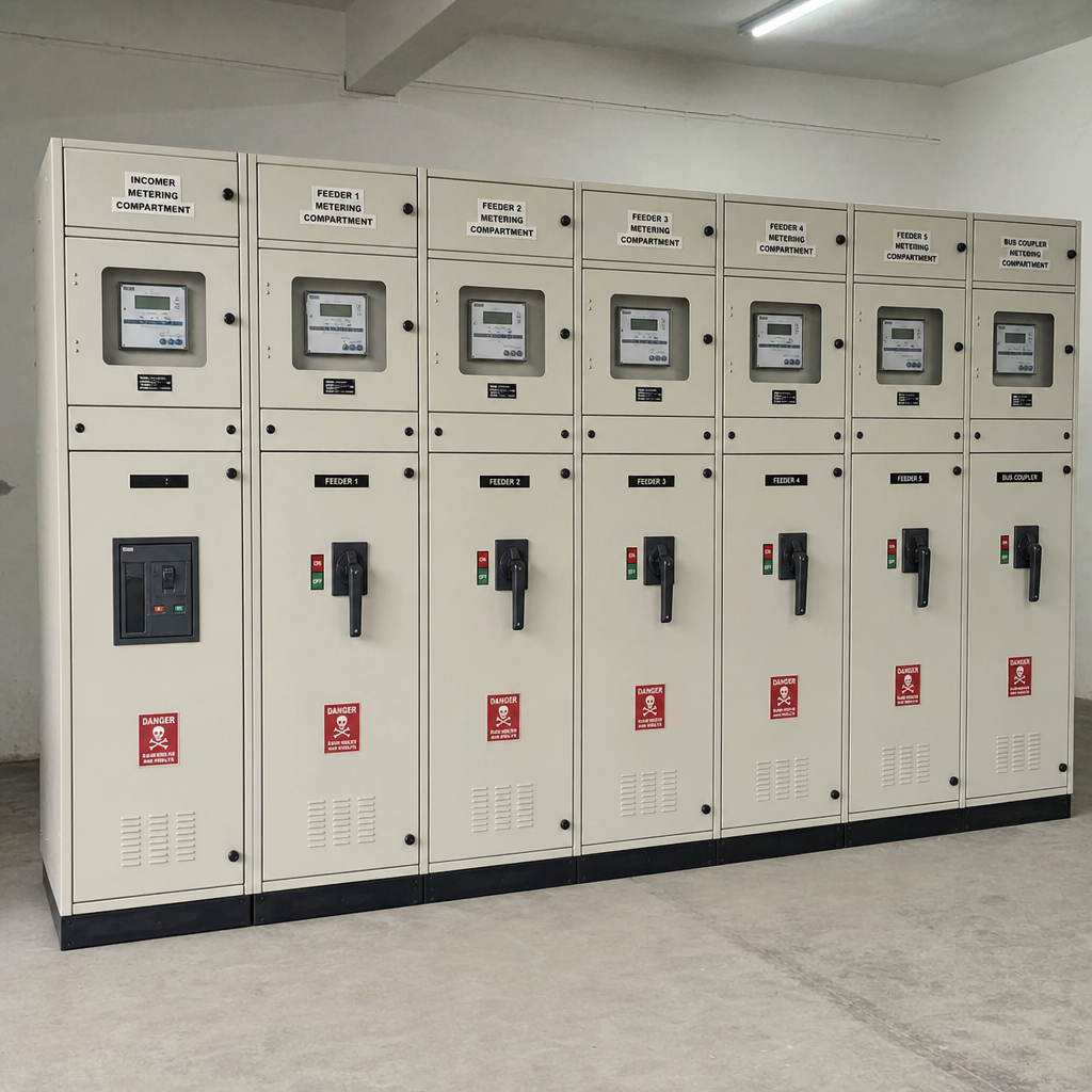
If you're building a panel from scratch, it's the best moment to standardize CT types, ratios, and classes. Nahu Group CTs are a straightforward fit for metering and protection architectures, helping you keep wiring consistent and documentation clean.
During design, align these decisions:
- CT type (solid core or split core CT depending on access and schedule)
- Ratio (e.g., 100/5A, 400/5A, 800/1A)
- Current transformer accuracy class explained (metering vs protection intent)
- Secondary burden and lead lengths (ties to burden calculations)
How to size current transformer (practical method)
Many engineers overcomplicate how to size current transformer. Use this field-proven approach:
- Measure or calculate max operating current (not just breaker rating).
- Add headroom for load growth and short-duration peaks (often 10–25% depending on context).
- Choose a CT ratio so normal load sits in the "sweet spot" of accuracy (often 20–100% of rated primary for metering CTs).
- Confirm the meter/relay expects 1A or 5A secondary.
Example: If a feeder normally runs 180A and can reach 240A, a 250/5A or 300/5A CT is often more meaningful than 200/5A (which may saturate or clip peaks).
Retrofitting: split-core CTs and minimal downtime
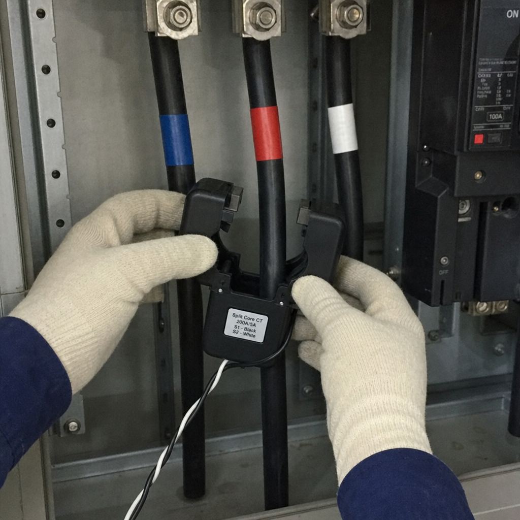
For existing facilities, access and downtime are everything. A split-core current transformer is the usual retrofit champion: you open the core, place it around the conductor, and close it — no disconnection required.
Retrofitting best practices:
- Match CT window size to cable OD (and consider parallel conductors)
- Keep polarity consistent (see polarity section below)
- Route secondary wiring away from noise sources and high heat
- Label phase (A/B/C) and circuit name at both ends
Current transformer wiring diagram essentials (and what usually goes wrong)
A correct current transformer wiring diagram is less about art and more about habits:
Standard CT wiring workflow
- Primary conductor passes through CT window (or bar-type primary).
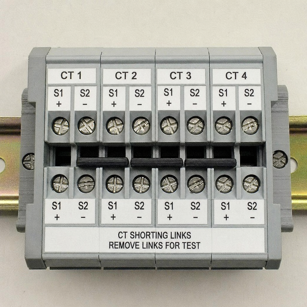
- CT secondary S1/S2 goes to meter/relay input (often via a shorting terminal block).
- If using multiple CTs, ensure phase A/B/C order matches voltage references.
Common pitfalls
- Open-circuiting a CT secondary under load (dangerous voltage can develop).
- Reversed polarity causing negative power readings.
- Excessive lead length increasing burden and distorting readings.
- Mixing phase mapping (A-phase CT on B-phase voltage reference).
CT polarity dot convention: don't guess
The CT polarity dot convention matters whenever directionality affects readings (power, power factor, demand). If polarity is wrong, you may see:
- Negative kW when load is clearly consuming
- Unstable or "flipped" power factor
- Odd three-phase vector sums
Rule of thumb: align dotted side (or marked S1/P1) consistently across phases and match the meter's documented input orientation.
Current transformer accuracy class explained (metering vs protection)
Accuracy class drives whether the CT is optimized for precise measurement at typical loads or for predictable behavior at high fault currents.
- Metering CTs: prioritize low ratio and phase error in normal operating range.
- Protection CTs: prioritize predictable saturation characteristics for relays.
When your goal is submetering or tenant billing, select a class aligned with metering performance and confirm installation burden doesn't push the CT outside spec.
Burden resistor selection guide (and why it affects accuracy)
CT secondaries must "see" an acceptable load (burden). Too much burden forces the CT to generate higher secondary voltage, increasing error and risking saturation.
A practical burden resistor selection guide mindset:
- First total the burden: meter input burden (VA), terminal blocks, and wiring resistance.
- Keep wiring short and use appropriate conductor size.
- If you're converting CT current output into a voltage for a controller/ADC, the burden resistor value sets the voltage level — and the burden VA.
Tip: If you're integrating with custom electronics (data loggers, microcontrollers), confirm whether you're using a current-output CT (needs burden resistor) or a voltage-output module design.
Current transformer saturation symptoms: how to spot trouble fast
Current transformer saturation symptoms often show up as "mysterious" measurement issues:
- kW/kVA flattening at high loads
- Distorted waveform on the secondary (if scoped)
- Rising error as current increases
- Protective relay misoperation in severe cases
Saturation is commonly caused by:
- CT ratio too small for peak currents
- Burden too high (long wires, wrong resistor, multiple devices)
- Incorrect CT class for the application
Clamp meter vs current transformer: when to use which
The clamp meter vs current transformer decision is simple:
- Use a clamp meter for quick diagnostics and spot checks.
- Use a fixed current transformer module for continuous monitoring, automation, or billing-grade metering.
Clamp meters are convenient, but permanent systems win on trend data, alarms, and integration.
How to test current transformer output (commissioning checklist)
Commissioning matters as much as hardware. Here's a concise method for how to test current transformer output:
- Visual: confirm ratio labels, phase labels, polarity marks, and that the core is fully closed (split-core latch seated).
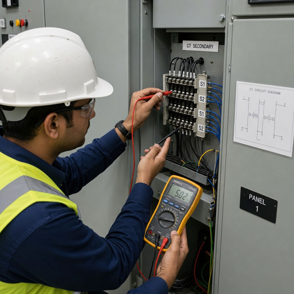
- Continuity: verify secondary loop continuity (with CT shorted and de-energized practices observed).
- Functional test: apply known load and compare meter reading to expected current (or compare with a trusted clamp meter).
- Vector sanity: in three-phase, verify phase sequence and balanced loads produce sensible totals.
Why current transformer reading zero (most common causes)
If you're troubleshooting why current transformer reading zero, check:
- CT secondary is open (broken wire, loose terminal, open shorting link)
- CT installed around the wrong conductor (neutral instead of phase, or only one of multiple parallel runs)
- Split-core not fully closed
- Meter configured for wrong input type (1A vs 5A)
- Incorrect channel mapping in the monitoring system
Rogowski coil alternative: when it makes sense
A Rogowski coil alternative can be attractive for flexible installation and very high currents, but it typically needs an integrator circuit and may not be as straightforward for traditional metering inputs. In many retrofit and standard panel builds, conventional CTs remain the most direct path to stable, standards-aligned metering.
Best current sensor for Arduino (and where CTs fit)
If you're searching for the best current sensor for Arduino, you're often balancing cost, isolation, and accuracy. CT-based sensing is popular because it offers isolation and scales to higher currents than many shunt solutions. A CT plus proper burden resistor and signal conditioning can feed an ADC safely — just remember you're building an isolated current sensing circuit, so treat grounding and scaling carefully.
For industrial deployments, however, it's usually better to keep DIY electronics at the edge and use proven CTs paired with industrial meters or gateways.
Nahu Group CT solutions: built for installation reality
Nahu Group current transformers are selected to support both new builds and upgrades — helping you standardize across sites and reduce commissioning risk. If you're specifying CTs for submetering, feeder monitoring, or multi-tenant energy allocation, start with Nahu Group's CT range and match:
- Ratio to real peak currents
- Accuracy class to metering/protection needs
- Mechanical format to your panel access (solid vs split-core)
Explore the product range here: Nahu Group Current Transformers
Takeaway
A well-chosen current transformer module is one of the highest-leverage upgrades you can make in electrical measurement: it improves safety, enables dependable energy analytics, and simplifies retrofit installations — especially with split-core current transformer options. Prioritize correct sizing, burden management, and polarity/phase mapping, and you'll avoid the most common commissioning failures while building a monitoring system you can trust.
Published August 11, 2026 · Nahu Group (NAHU Electric Technology)