
A split core current transformer is an instrument transformer with a two-part, hinged magnetic core that opens so the device can be placed around an existing cable or busbar and then closes to form a complete magnetic circuit. Because it does not need to be threaded over the conductor before termination, it is the practical choice whenever a current transformer must be added to a circuit that is already built, already energized, or too difficult to disconnect.
Whereas a solid-core or bar-type current transformer must be installed while the conductor is disconnected and re-terminated, a split-core CT simply closes around the conductor in place. The primary circuit is not broken, the outage window shrinks from hours to minutes, and the installation is reversible if the measurement point needs to change later.
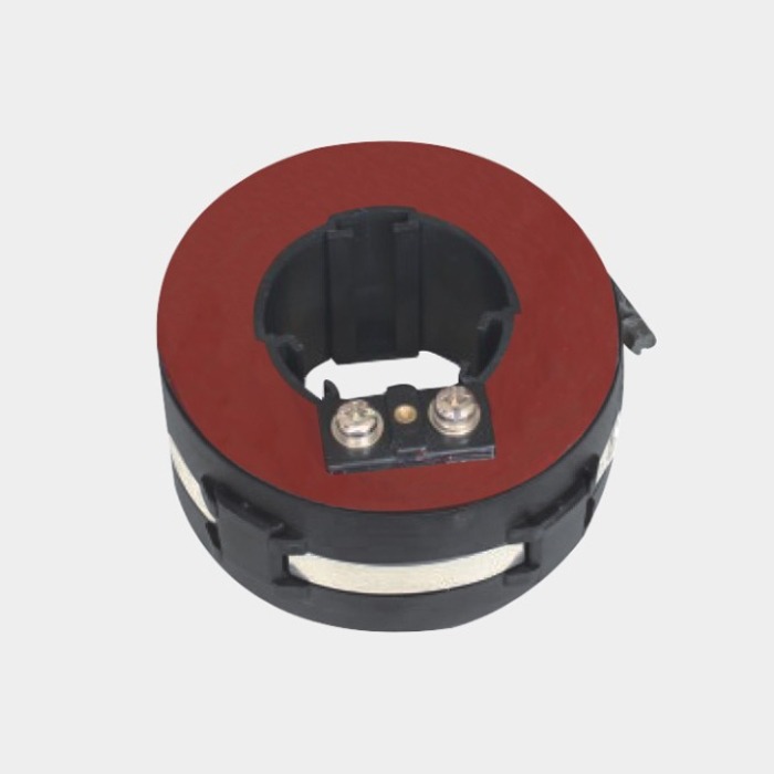
What is a split core current transformer?
Like any current transformer, a split-core CT reduces a large primary current to a small, standardized secondary current for meters, relays, and monitoring instruments. The name comes from the core construction. Instead of a single continuous ring of grain-oriented steel, the core is manufactured in two halves. One half carries the secondary winding, and both halves meet at precisely machined surfaces so the core can be opened like a clamp.
In service, the conductor being measured acts as the single-turn primary winding. When the core is closed, the magnetic circuit is complete and the secondary winding produces an output proportional to the primary current. This is the same operating principle as a window or ring-type CT; the difference is mechanical. That is why split-core transformers are also described as open-core current transformers.
How does a split-core CT work?
Installation follows a simple sequence. First the secondary terminals are connected to a meter, relay, or shorting device so the secondary always has a current path. The hinged core is then opened, positioned around the cable or busbar at the chosen point, and closed until the two faces align. A latch or clamp holds the halves together against vibration and thermal cycling.
With the core closed, the conductor behaves as one primary turn and the secondary winding delivers current according to the CT ratio. Because the device always sees a single primary turn, the ratio is effectively set by the number of secondary turns, which is why manufacturers can offer a range of ratios for one bore size.
One safety rule applies to every current transformer, split-core included: never open the secondary circuit while primary current is flowing, or a dangerously high voltage can appear across the terminals. Before opening the clamp to relocate or remove the device, short-circuit the secondary at a proper terminal block and de-energize the primary whenever possible.
Where split core current transformers fit in practice
Split-core CTs earn their place wherever measurement must be added to plant that is already running, densely packed, or expensive to take out of service — where the real cost of a conventional CT installation is the outage and the cable work, not the component.
- Retrofit metering: Adding energy meters or sub-meters to existing feeders and distribution boards so consumption can be allocated by tenant, process, or cost center.
- Energy audits: Installing temporary or permanent current sensing to establish a consumption baseline for a plant, line, or machine before efficiency investment decisions are made.
- Load monitoring: Trending current on distribution circuits to confirm spare capacity, detect emerging overloads, or verify demand behavior.
- Protection and monitoring upgrades: Providing current signals to relays and monitors on older switchgear where the original CTs have no spare cores, the wrong ratio, or insufficient accuracy.
- Portable instrumentation: Supporting commissioning checks, power quality surveys, and temporary studies where the sensing point must change between circuits.
The rule of thumb is simple: if the conductor can be reached with an open clamp, a split-core CT can usually be fitted — even where a solid-core CT could not be installed after the fact.
Accuracy and ratio considerations
Selection starts with what the signal will feed, because a meter and a relay ask different things of the same CT. Metering demands faithful reproduction of current across the normal operating range, where small percentage errors become billing and energy errors. Protection demands a usable signal at high fault multiples, without saturating too early.
Measuring accuracy classes
Measuring classes such as 0.5, 1.0, and 3.0 express the maximum ratio error allowed at the rated current and burden. A lower number means a more accurate transformer. For billing, sub-metering, and energy audits, a better class usually pays for itself because the error repeats every hour the circuit runs.
Protection classes
Protection classes such as 5P and 10P define how much composite error the transformer may show up to its rated accuracy limit. A 5P class limits composite error to five percent and a 10P class to ten percent under the specified fault conditions, which lets the protection engineer coordinate relay settings with some confidence. Where one device must serve both duties, a CT with separate measuring and protection cores is the clean solution.
Ratio selection is equally practical. The primary rating should sit above the maximum expected load current so the core is not pushed toward saturation in normal service, but not so far above it that light loads fall into the least accurate part of the range. The secondary rating, commonly 5 A or 1 A, should match the meter or relay inputs and the acceptable voltage drop over the secondary wiring.
Split core current transformer selection checklist
A structured checklist keeps a retrofit project from stalling at the panel. Before requesting a quotation, confirm each of the following against the actual installation.
- Bore or window size: The open window must clear the cable diameter, cable lug, or busbar cross-section, with allowance for insulation and bending radius.
- Primary current: The rating should cover the maximum expected load with margin, while keeping normal operating current inside the accurate portion of the range.
- Ratio and secondary output: Choose the ratio and secondary current that match the meter, relay, or logger inputs and the length of secondary wiring.
- Measuring or protection core: Specify whether the signal serves metering, protection, or both, and confirm the accuracy class needed for the duty.
- Burden: Add the VA demand of the connected instruments to the burden of the interconnecting leads; the class is only valid when the connected burden stays within the rated burden.
- Insulation and environment: Consider system voltage, indoor or outdoor location, temperature, humidity, and pollution so the device suits the real service conditions.
- Access and fixing: Check that the hinge opens the way you need it to, that there is clearance to close and latch the core, and that terminals stay reachable and safe.
Because a split-core CT is physically fitted to the actual conductor, confirm bore size and orientation against site drawings or a photograph before ordering.
LMZK-10 split core current transformer from Nahu Group
The Nahu LMZK-10 is a split-core, or open-core, current transformer that clamps around an existing cable or busbar and can be installed without breaking the primary circuit. It is specified for retrofit metering, energy audits, and protection and monitoring upgrades on existing equipment. Measuring accuracy classes of 0.5, 1.0, and 3.0 are offered alongside protection classes of 5P and 10P, and multiple ratios and bore sizes are available on request so the unit can be matched to the conductor and the duty at hand.
The LMZK-10 comes from Nahu Group (NAHU Electric Technology), an instrument transformer manufacturer based in Yueqing, China, that has served the industry since 2008. The company is ISO 9001 certified, its products are type-tested to IEC 61869, and it supplies customers in more than 40 countries with a product range spanning 3 kV to 40.5 kV. To compare the LMZK-10 with other specialty sensing options, browse the specialty and busbar product category, or contact the engineering team with your cable size, load current, and meter or relay details for a recommendation.
When metering must be added to a feeder that cannot be taken out of service, a split core current transformer is the fastest, lowest-risk route to a dependable current signal: choose the bore for the conductor, the class for the instrument, and the ratio for the load, and the retrofit becomes a short, reversible job rather than a shutdown project.
Published September 2, 2026 · Nahu Group (NAHU Electric Technology)