
A load break switch fuse combination is set by one number most enquiry sheets leave blank: the transfer current. Fix that number and the fuse clears every fault the network can deliver; leave it blank and the switch is asked to interrupt a fault it was never tested to break, which is the failure the combination exists to prevent.
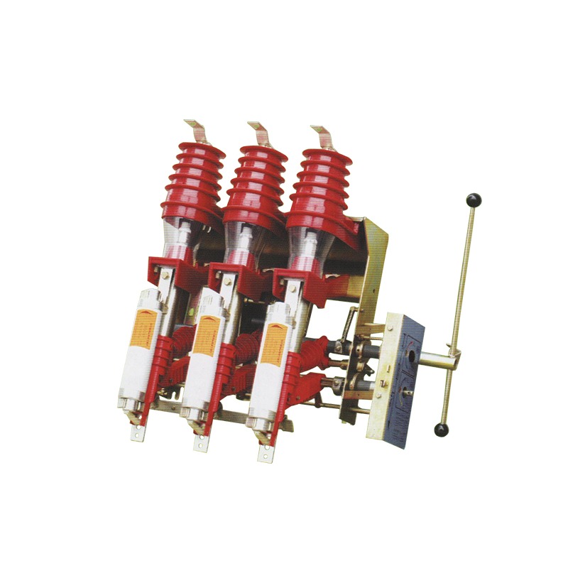
What Does the Load Break Switch Fuse Combination Actually Protect?
Two devices in series, doing two different jobs. The switch handles normal service: load current, closed-loop current between feeders, and the charging current of cables and unloaded transformers. The fuse handles the one event the switch cannot, a short circuit, and it does so by melting, so it works once.
That division is why a combination can replace a circuit breaker on a distribution tee-off at a fraction of the cost. It is also why the division has to be written down as a number rather than assumed. Nahu Group builds the arrangement this way in its load break switch range, with the fuse mounted on the same frame as the interrupter.
Where Does the Fuse Stop and the Switch Start?
IEC 62271-105 defines the transfer current as the current the combination can transfer from the fuse to the switch, and requires a type test at that value. Below it, the switch can open the circuit after the fuse starts to operate. Above it, the fuse must clear alone.
Two consequences follow, and they pull in opposite directions:
- Prospective fault current must stay above the transfer current. If a rural feeder can deliver only 900 A at the tee-off and the combination is declared at 1,600 A, the fuse may not clear before the switch is required to act.
- The transfer current belongs to a specific fuse. Change the link and the declared value changes with it, so a substitution at site quietly invalidates the coordination that was approved.
In a load break switch fuse combination that boundary is a tested number, not a preference. State the minimum and maximum prospective fault current at the tee-off, ask for the transfer current declared with the fuse you intend to use, and require the type test report covering that pairing. The switch mechanism is covered separately by IEC 62271-103.
The interruption principle does not change this logic, but it changes the maintenance story. Vacuum interruption keeps the arc inside a sealed bottle with no gas handling; compressed air uses a small blast and a set of arc chutes that are inspected and cleaned. Either way the fuse barrel sits downstream of the switch, and it is the part that clears the fault current the switch itself cannot interrupt.

Which Fuse Rating Suits Which Transformer?
Size the fuse against the transformer, not the switch. Start from primary full-load current and work at roughly 1.5 to 2 times that value: high enough to ride through magnetising inrush, low enough to protect the winding. The arithmetic below is for 11 kV, and it is a starting band for the fuse curves, not a substitute for them.
| Transformer rating | Primary full-load current at 11 kV | Working band for the fuse link | What decides the final value |
|---|---|---|---|
| 315 kVA | 16.5 A | 25–40 A | Inrush duration and the upstream relay curve |
| 500 kVA | 26.2 A | 40–63 A | Cold-load pickup on a rural feeder |
| 630 kVA | 33.1 A | 50–80 A | Ambient derating inside the enclosure |
| 800 kVA | 42.0 A | 63–100 A | Transformer impedance and let-through energy |
| 1,000 kVA | 52.5 A | 80–125 A | Coordination with the LV main breaker |
| 1,250 kVA | 65.6 A | 100–160 A | Whether the combination is declared at that transfer current |
Two checks sit on top of the band: let-through energy at the prospective fault current must stay under the withstand of cable and switch frame, and the curve must give the selectivity upstream protection expects. The second is covered in the K-type versus T-type fuse link comparison.
Which Fuse Characteristic Has to Match the Transformer?
A fuse that suits the transformer can still be wrong for the combination. Three characteristics are usually left unstated and should be fixed before quotations are compared:
- Rated current and voltage, at the ambient the fuse actually sees inside the enclosure rather than the ambient of the site.
- Minimum breaking current, because a link that cannot clear a low fault current leaves an arcing fault with no device willing to take it.
- Striker operation, if the mechanism should trip all three poles when one fuse operates. Without it, a single-phase failure leaves the transformer running on two phases.
Where Does a Fused Combination Sit Relative to the Isolator?
A load break switch fuse combination does not replace the visible isolation an operator needs before touching the cable. On pole-mounted and outdoor arrangements the isolating function normally sits upstream as a separate three-pole disconnector, so the fused switch can be worked on with a visible break in series.
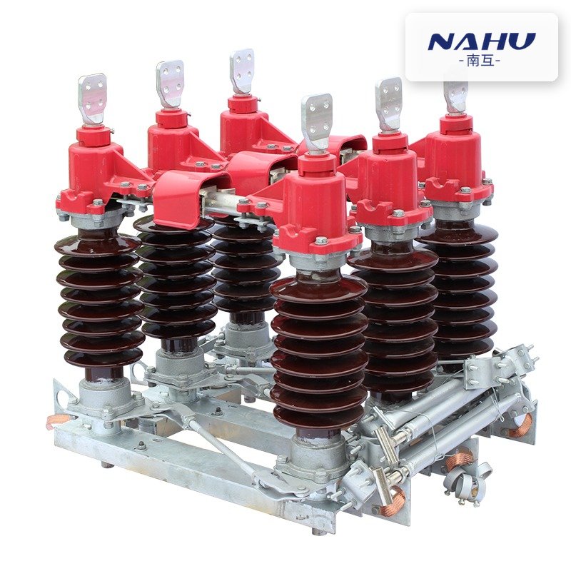
Keeping the two duties separate matters at commissioning as much as at maintenance. The isolator provides the visible break the switching schedule names; the combination provides load breaking and fault clearing. Writing both into the single-line diagram prevents the situation where an operator is asked to open a disconnector on load. The difference is set out in whether a disconnect switch can break load current.
Which Mistakes Show Up at Commissioning?
Most failures traced back to a load break switch fuse combination are coordination decisions taken on a datasheet nobody re-checked, not manufacturing defects:
- Fuse upsized on site to stop nuisance tripping, which moves the transfer current and leaves the combination outside its tested pairing.
- Fault level assumed, not measured. A tee-off near a substation and the same tee-off three kilometres down the feeder are not the same application.
- Fuse ambient ignored. A 100 A link inside a sealed enclosure in a 45 °C ambient is not a 100 A link.
- No striker. The protection works, the transformer keeps running on two phases, and the burnt winding is found weeks later.
The consequence is rarely the price of a fuse. It is a rejected inspection, a re-test, or a delayed energisation while the correct link is flown in.
What Should the RFQ or Datasheet State?
A combination enquiry that states the following lines can be quoted and type tested against without a clarification round. The shared service-condition definitions sit in IEC 62271-1.
| Datasheet line | What to write | Why it changes the offer |
|---|---|---|
| Rated voltage and frequency | 12 kV, 50 Hz, system earthing arrangement | Fixes insulation level and arrester coordination at the node |
| Rated current | 630 A busbar and tee-off, continuous | Sets the frame and terminal size |
| Transfer current | Declared value with the specified fuse, plus the type test report | Decides whether fuse or switch clears the fault |
| Fuse | Rated current, type, striker, standard | Changes the declared transfer current and tripping behaviour |
| Fault level | Minimum and maximum prospective current at the tee-off | Proves the combination sits inside its tested window |
| Duty | Load break, closed loop, cable charging, earthing switch rating | Selects vacuum or compressed-air interruption |
| Environment | Ambient, pollution level, altitude, enclosure IP | Derates fuse and insulation |
| Documents | Type test reports, routine test report, drawings for approval | Decides whether the package passes inspection |
On a 33 kV network the same lines apply with different numbers, and the logic is set out in the 33 kV load break switch selection guide. What the switch does on a ring, independent of the fuse, is covered in the load break switch working guide.
Where Nahu Group Fits
Nahu Group makes the FZN25-12 vacuum load switch and FZRN25-12 combined fuse appliance for 12 kV ring networks and terminal supplies, with manual or electric operation and a grounding valve linked to the earthing switch. The FKN12A-12 and FKRN12A-12 compressed-air load switch covers projects that specify that interruption principle. Both are supplied as bay devices, so enclosure, cable compartment and interlocking arrive as one package.
To get a configuration, send the single-line diagram, transformer rating, prospective fault current at the tee-off, the fuse type you intend to use, ambient and pollution level, and whether remote operation is needed. With those six items the transfer current and the fuse pairing can be confirmed in writing before the order is placed.
Frequently Asked Questions About Load Break Switch Fuse Combinations
What is the transfer current in a switch-fuse combination?
It is the fault current at which the duty of clearing moves from the switch to the fuse, declared by the manufacturer for a specific fuse and proved by type test. Below that value the switch can open the circuit safely after the fuse starts to operate; above it the fuse must clear alone, before the switch is called on.
How do I size a fuse for a 630 kVA transformer at 11 kV?
Start from the primary full-load current, about 33 A at 11 kV, and work in the 50 to 80 A band. Then open the fuse curves and confirm two things: the link rides through transformer inrush without operating, and its let-through energy at the prospective fault current stays below the cable and switch withstand.
Can a higher-rated fuse be fitted on site to stop nuisance tripping?
Not without re-checking the coordination, because the declared transfer current belongs to the fuse that was type tested with the switch. A larger link shifts that boundary, raises the let-through energy and may leave the installation outside its tested pairing. Tripping is usually solved by correcting the fuse ambient assumption, not by increasing amps.
Does a fused load break switch still need a separate isolator?
Yes, where the switching schedule requires a visible break before work on the cable. The combination provides load breaking and fault clearing, not a visible isolating distance. On pole-mounted and outdoor arrangements the disconnector is normally a separate three-pole device upstream, interlocked with the switch.
Which test report should the supplier submit?
A type test report to IEC 62271-105 that covers the exact switch and fuse pairing offered, plus routine test reports for the units shipped. A report for the switch alone does not demonstrate the transfer behaviour, and reports issued for a different fuse rating do not cover the substitution.
Sources and Further Reading
- IEC 62271-105:2021 — High-voltage switchgear and controlgear, Part 105: Alternating current switch-fuse combinations for rated voltages above 1 kV up to and including 52 kV — defines the transfer current, the duties a combination is type tested for, and the fuse pairing that the declared ratings belong to
- IEC 62271-103:2021 — High-voltage switchgear and controlgear, Part 103: Alternating current switches for rated voltages above 1 kV up to and including 52 kV — the type-test standard for the load-breaking and closed-loop duties the switch itself must prove
- IEC 62271-1:2017 — High-voltage switchgear and controlgear, Part 1: Common specifications for alternating current switchgear and controlgear — the service conditions, ambient and pollution levels, and the shared rating framework the combination is declared against
Published Nov 11, 2026 · Nahu Group (NAHU Electric Technology)