
A load break switch 33kV networks can rely on is specified by fixing five parameters before any offer is compared: rated voltage class, rated normal current, rated short-time withstand current with its duration, rated short-circuit making capacity, and number of poles. Mounting, operating mechanism, earthing switch interlocking and external insulation all follow from those five decisions plus the conditions of the site.
Most rework in medium-voltage switching enquiries happens because a parameter was left for the supplier to guess, or a mounting arrangement was chosen before the switching duty and the site exposure were understood. This guide follows the selection sequence for a 33 kV-class network in the order a project engineer has to close it out.
If the basic definition is still open, start with what a load break switch is and how it differs from a circuit breaker and an isolator; the isolating switch guide covers the disconnector side of the same switchboard.
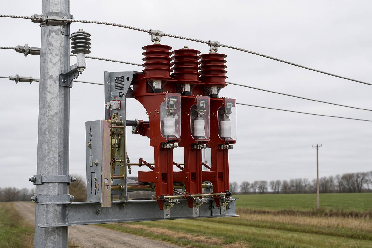
Which Parameters Must a Load Break Switch 33kV Specification Fix?
Every parameter you fix constrains the type test evidence a supplier may quote. The table follows the order in which those decisions are normally settled: fault study, continuous current, switching duty, then the mechanical choices.
| What it defines | What the engineer must confirm | |
|---|---|---|
| Rated voltage class | Insulation class the switch is designed and type tested for | That it matches this network, not a neighbouring voltage level |
| Rated normal current | Continuous current carried within the temperature limits | That it covers the feeder or transformer rating, including planned uprating |
| Short-time withstand current and duration | Fault current carried while protection clears the fault | The value from the fault study, and the duration the governing standard edition uses |
| Short-circuit making capacity | Highest current the switch can close onto | That it is not confused with the withstand value, which is a different event |
| Number of poles | Three-pole or single-pole operation | Whether any part of the network uses single-phase switching |
| Insulation level | Withstand across the open gap and to earth | The insulation co-ordination study, including altitude and surge exposure |
| Rated frequency | System frequency the design assumes | That it matches the network the switch will be installed on |
Two of these are routinely under-specified: the duration attached to the short-time withstand current, because the current alone is an incomplete rating; and making capacity, often omitted because the switch is treated as an opening device, even though a switch closed onto a live circuit must make current.
The standard family governing this class is IEC 62271-103, which the IECEE catalogue describes as covering alternating current switches for rated voltages above 1 kV up to and including 52 kV. Until the edition and any national deviation are named, data sheet ratings cannot be compared like for like, so treat the edition as a deliverable rather than a footnote.
What Do Load Break Switch Ratings Actually Describe?
Ratings answer three separate questions. The first is thermal: how much current is carried continuously, and how much fault current briefly while protection operates — values set by conductor cross-section, contact design and the heat path out of the enclosure.
The second is switching capability: what current the switch opens and closes under normal and faulted conditions, and how many such operations the design is demonstrated for. A switch that opens loaded feeders daily carries a different duty from one operated twice a year.
The third is insulation: what voltage is withstood between live parts, across the open gap and to earth, and how that withstand degrades as pollution and condensation accumulate — treated in the creepage section below, because on a coastal or industrial site it often decides the enclosure.
Match every quoted rating to the type test that demonstrates it, because a rating without test evidence is a design intention. Buyers who also need the switching-medium question answered separately can read the SF6 and vacuum load break switch comparison.
Indoor vs Outdoor vs Pole-Mounted: Which Mounting Does the Project Need?
This is the decision that costs most to reverse. An indoor vs outdoor load break switch comparison is not only about weather protection: it changes who may operate the switch, how earthing is arranged, what civil works are needed and which conditions the external insulation has to survive. A pole mounted load break switch moves the switching point onto the overhead line and removes the substation building altogether.
| Indoor | Outdoor on a structure | Pole-mounted | |
|---|---|---|---|
| Where it sits | Substation building, kiosk or switchgear room | Yard or platform, open or enclosed | On the pole, in the overhead line |
| Switching duty | Fixed position in a busbar or ring arrangement | Sectionalising position with room for accessories | Line sectionalising, isolating a spur or transformer |
| Access to operate | Controlled access by trained staff | Site access, platform or remote control | Pole access, hook stick or remote actuator |
| Enclosure and ingress | Building provides the protection | Enclosure driven by dust, rain and pollution | Must tolerate wind, rain, ice and solar heating |
| Earthing | Earthing switch in the panel, interlocked with the door | Separate or integrated earthing switch, visible break | Portable or hook-operated earthing devices |
| Main constraint | Space and cost of the building | Site exposure and clearance envelope | Limited room for interlocks and drives |
Choose indoor when the switching point is part of a larger assembly operated from one place. Choose an outdoor structure when the function stands alone and there is room for a safe operating envelope. Choose pole mounting to sectionalise an overhead line with minimum civil work, where pole access is acceptable.
The mounting also changes the fault current path through the switch and the pollution and condensation the insulation sees, so a design that is adequate in a clean, dry switchgear room is not automatically adequate on a pole in a coastal or dusty location. Nahu Group manufactures 10–35 kV distribution equipment, including load break switches and pole-mounted switching arrangements, but the site conditions on the specification still have to come from the project.
Which Operating Mechanism Should the Switch Use?
Manual operation keeps the device simple but depends on a competent person being present. A stored-energy spring mechanism makes the stroke independent of how hard the operator pushes, which matters for consistency across many operations. Motor operation adds remote control and raises questions about control supply, position indication and how remote operation is interlocked with local safety rules.
Three questions usually settle it: how often the switch operates, whether a reliable control supply exists at the site, and who may operate the device. Remote operation is only safe when its interlocks and signalling are at least as good as the procedures they replace. Decide the operating interface at the same time — hook stick, ground-level lever or keyed handle — because on pole-mounted installations it drives the cross-arm geometry.
How Does Earthing Switch Interlocking Define the Switching Sequence?
Earthing switch interlocking is what makes a safe switching sequence physically possible. The sequence is familiar: open the load break switch, confirm the open position, earth the isolated section, work under safety documents, then remove the earths and restore. Interlocking prevents the two steps that turn that sequence into an accident — earthing a section that is still live, and closing the switch while the earths are applied.
Interlocks work mechanically, so the block exists even if the procedure is not followed; by trapped keys, which transfer permission between devices that may sit far apart or in different panels; or electromagnetically, using a voltage or live-line condition, which matters when an earth may only be applied once the section has been proved dead. Modern assemblies usually combine all three.
Interlocking is not a price-trimming option. The 2018 edition of IEC 62271-102, the standard for alternating current disconnectors and earthing switches, added withstand requirements for interlocking devices and a subclause for testing mechanical interlocking devices, so the interlock is a tested part of the switch. That edition also extended its scope to switching devices that combine disconnecting or earthing functions with other functions, so state which interlocks are required and between which pairs of devices.
How Do Clearance and Creepage Change With the Voltage Class?
Clearance is the distance through air — between phases, between live parts and earth, and across the open gap. Creepage is the distance along an insulating surface from a live part to earth, measured over the profile rather than through it. Both scale with the voltage class, so the size of the switch does too.
Creepage is the one that surprises buyers, because the voltage class alone does not fix it: the distance needed along a surface depends on how polluted that surface becomes. IEC TS 60815-1, the specification for selecting and dimensioning high-voltage insulators intended for use in polluted conditions, sets out how site pollution severity is characterised and how a unified specific creepage distance is derived and corrected for shed profile, diameter and altitude. The same nominal voltage can therefore need visibly different external insulation on the coast than in clean rural air.
Three things therefore belong in the specification: creepage and clearance figures stated explicitly rather than inferred from enclosure size; a description of the pollution environment for the supplier to confirm against; and a named standard edition, because specific creepage values sit in the standard and a figure copied from another project is not evidence.
How Should You Compare Load Break Switch Selection Options on Paper?
Selection becomes straightforward once the requirements are written down in the same order as the parameters above. A short scoring sheet is enough, and it protects the project when the cheapest offer arrives.
- Voltage class and insulation level — does the quoted class match this network, with a type test for the site conditions?
- Continuous current and fault duty — normal current, short-time withstand current with its duration, and making capacity, each checked against the network study.
- Switching and mechanical duty — operations per year, of what kind, and what the design is demonstrated for.
- Mounting and operating access — indoor, outdoor or pole-mounted, with an interface the maintenance team can reach.
- Interlocking and earthing — which earths exist, which interlocks are required, and the duty of the earth path.
- External insulation — creepage and clearance stated against a named pollution environment and standard edition.
- Evidence and documentation — type test reports, drawings, rating plates, operating instructions and the maintenance schedule.
Run that sheet against two or three suppliers and the comparison stops being about price: it becomes a comparison of which supplier has documented the duty the network actually imposes. Nahu Group, which manufactures 10–35 kV distribution equipment such as load break switches and ring main units, quotes against a requirement list of this kind.
What Should a 33 kV Load Break Switch Enquiry Contain?
A complete load break switch 33kV enquiry lets a supplier answer with a specific configuration instead of a family brochure. Include the items below, marking anything still provisional.
- System data — nominal voltage, highest system voltage, frequency, earthing arrangement of the network.
- Ratings required — normal current, short-time withstand current with its duration, and making capacity, each with the source calculation.
- Poles and configuration — three-pole or single-pole, and the arrangement the switch sits in.
- Mounting — indoor, outdoor on a structure or pole-mounted, with pole details where relevant.
- Connection interface — cable or busbar connection type, terminal arrangement and the room available.
- Operating mechanism — manual, spring or motor operated, the operating interface, and whether remote control and position signalling are needed.
- Earthing and interlocking — whether an earthing switch is required, its duty, and the interlocks required with their logic.
- Environment — pollution environment, altitude, ambient temperature range, humidity, seismic requirement and any ingress protection needed.
- Standards and evidence — the standard edition and national deviation the project follows, and the type test evidence expected.
- Destination and documentation — destination market, required language for manuals and rating plates, and any witnessing requirement.
Attach a single-line diagram even if the ratings are still being calculated: it settles mounting, earthing and interlocking faster than a page of description.
Sources and Further Reading
- IECEE — IEC 62271-103:2021, alternating current switches for rated voltages above 1 kV up to and including 52 kV
- IECEE — IEC 62271-102:2018, alternating current disconnectors and earthing switches
- IEC — IEC TS 60815-1:2025, selection and dimensioning of high-voltage insulators for polluted conditions
- KEMA Labs (CESI) — testing to IEC 62271-103 for alternating current switches up to 52 kV
Frequently Asked Questions
Can a load break switch be used on a 33 kV network?
Yes. IEC 62271-103 covers alternating current switches for rated voltages above 1 kV up to and including 52 kV, so a 33 kV-class network sits inside its scope. What matters is that the device is type tested for the voltage class, insulation level and fault duty of your own network.
What is the difference between rated normal current and short-time withstand current?
Rated normal current is the continuous current the closed switch carries without exceeding its temperature limits. Short-time withstand current is the fault current it carries for a short, defined duration while upstream protection clears the fault. The first sizes the conductors and the heat path; the second shows that the switch survives a fault passing through it.
Why is short-circuit making capacity specified separately from the withstand current?
They describe different events. Withstand current is about carrying a fault that already exists elsewhere on the circuit. Making capacity is about closing the switch onto a live circuit or onto a fault, which asks the contacts to establish a current rather than merely carry it. A switch used for looping or restoring a feeder must be able to make current.
When is a pole-mounted load break switch the right choice?
Pole mounting suits sectionalising an overhead line or isolating a spur or transformer without building a substation. It keeps civil works to a minimum and places the switching point where the line already is. The trade-offs are access, because operating and maintaining the device means working at the pole, and less room for drives, interlocks and accessories.
What does earthing switch interlocking actually prevent?
It prevents the two combinations that make an otherwise correct switching sequence dangerous: applying the earth while the section is still live, and closing the load break switch while the earths are still connected. The interlock is implemented mechanically, with trapped keys, by an electromagnetic condition, or by a combination of the three.
Can the earthing switch be combined with the load break switch?
Often, yes. The 2018 edition of IEC 62271-102 extended its scope to cover switching devices that carry disconnecting or earthing functions alongside other functions. When a combined device is used, describe the required interlocking logic in the specification, because the internal arrangement is not visible on an enquiry drawing.
How do I know which creepage distance to specify?
Start from the pollution environment of the site rather than from a figure copied from another project. IEC TS 60815-1 describes how site pollution severity is characterised and how the required specific creepage distance is derived from it and corrected for shed profile, diameter and altitude. Require clearance and creepage values to be stated against the standard edition your project follows.
What information makes a load break switch enquiry easy to quote?
System voltage and frequency, rated normal current, short-time withstand current with its duration, making capacity, number of poles, mounting arrangement, connection type, operating mechanism, earthing and interlocking requirements, site environment, and the standard edition and national deviation the project follows. A single-line diagram attached to that list removes most follow-up questions.
Closing the Selection Loop
Selection on a 33 kV-class network is a short chain of decisions, each with a document behind it: the fault study fixes the fault ratings, the load flow the continuous rating, the operating regime the mechanism, the site the mounting and insulation, and the safety procedure the interlocking. Fix them in order and offer comparison becomes a check rather than a debate.
For projects in this band, Nahu Group manufactures 10–35 kV distribution equipment, including instrument transformers, metering boxes, load break switches, ring main units, vacuum circuit breakers, surge arresters, drop-out fuses and cable branch boxes. The load break switch range shows the configurations available, and sending the single-line diagram with the ratings above is usually enough to confirm what fits.
Published September 23, 2026 · Nahu Group (NAHU Electric Technology)