
No — a disconnect switch cannot be opened on load current, and the reason is mechanical rather than administrative. It has no arc-quenching chamber: when the blades part under load the arc is drawn in open air, and it lasts until the current passes through zero and the gap is long enough to withstand the recovery voltage. At load current that gap often is not reached before the arc has damaged the contacts or flashed across to the adjacent phase.
What an isolator can break is the small current its manufacturer has declared and tested — busbar charging current, the magnetising current of an unloaded transformer, a short length of cable. Those declared values are specific to the product and the circuit, and they belong on the datasheet, not in an operator's experience.
What the Arc Does to the Contacts
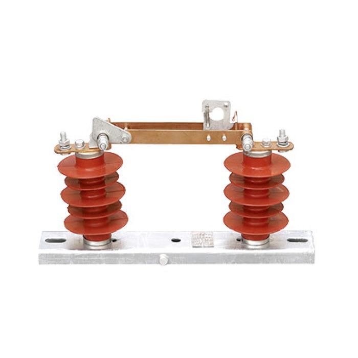
On a load-break switch, the arc is drawn inside an arc chute or a sealed interrupting chamber and is cooled, split and deionised within milliseconds. A disconnect switch has none of that. The arc roots sit on the blade tip and the fixed contact, and they move as the blade opens.
- Contact erosion. Each operation at current removes silver or copper from the contact faces. A few operations on load current will pit a surface that is designed to stay smooth for thousands of no-load operations.
- Lost contact pressure. The eroded face no longer seats flat, so the contact pressure that the spring was set to falls, and the joint runs hotter at normal load.
- Phase-to-phase flashover. In an air-insulated outdoor isolator the arc elongates with the blade and can transfer to the neighbouring phase or to earth, which turns a switching operation into a fault on the busbar.
- Damage that inspection will find later. The pitting is visible at the next maintenance visit, and by then the question is not whether the switch may be used but whether it must be replaced.
Which Operations Are Actually Permitted
| Operation | Permitted for a disconnect switch? | What it depends on |
|---|---|---|
| Opening a section of busbar with no load connected | Usually yes | The declared busbar charging current must exceed what the section draws |
| Opening the supply to an unloaded transformer | Usually yes | The declared magnetising current on the datasheet, at the transformer rating you have |
| Opening a loaded feeder or a transformer carrying load | No | Load current is far beyond any declared breaking value |
| Splitting a ring or a loop under load | Only where loop splitting is declared | Most units carry no such declaration; check the test report before the procedure is written |
| Switching a capacitor bank | No | Capacitive current and restrike risk are outside the isolator's duty |
| Closing an earthing switch onto a live circuit | Never | This is not a breaking duty at all; the interlock exists to prevent it |
The operational rule that follows is simple and should be written into the switching schedule: break the current with a device that is rated to break it, then use the isolator to establish a visible gap. The isolating switch guide covers the indoor and outdoor types and where each is used; the load break switch guide covers the device that does the interrupting.
The Real Boundary on Site
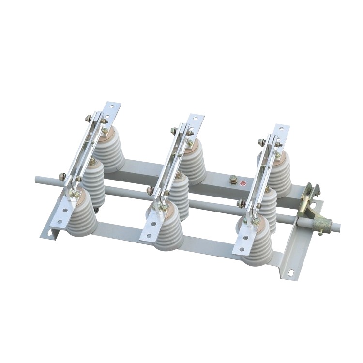
In a properly designed scheme the operator cannot make the mistake, because the interlock prevents it. A disconnector is mechanically interlocked with the circuit breaker or load break switch in series with it, so the isolator cannot be opened while the interrupting device is closed. Where that interlock is missing, bypassed or "temporarily" defeated during commissioning, the rule falls back on the person holding the handle.
Three situations put the isolator under load in practice, and all three are procedure failures rather than equipment failures: a switching schedule written without checking which device breaks current, a breaker that failed to open so the isolator became the only means of isolation, and a maintenance practice of "just cracking the blades" to prove the circuit is dead. The third is the most dangerous, because it produces an arc in front of the person doing it.
Contact Condition Is a Maintenance Item, Not a Given
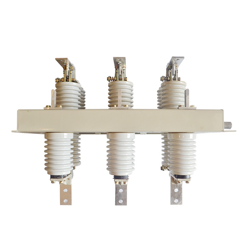
Because the isolator has no arc control, its contacts are the whole story. On outdoor units the mechanism is exposed to dust, salt and thermal cycling, and on indoor units to the same load cycles without the weather. Inspection should look at the contact faces for pitting, the blade alignment, the pressure springs and the condition of the hinge and bearings, and it should record contact resistance where the design provides a test point.
Two symptoms justify taking a unit out of service rather than adjusting it: a contact that runs visibly hotter than its neighbours under the same load, and an operation that no longer produces a clean, definite end position. Both point to a mechanism that has lost the geometry it was set up with, and no amount of cleaning restores that.
What to Put in the Specification
The isolating switch range covers indoor and outdoor types for distribution networks, and the enquiry has to state the duty rather than just the model:
- Rated voltage and rated current, with the highest system voltage named separately.
- Rated short-time withstand current and duration, which is the duty the switch carries while the upstream protection clears a fault.
- Any declared breaking capacity, stated per application — charging current, magnetising current or loop splitting — with the test evidence.
- Indoor or outdoor, pollution level, and the creepage distance in millimetres.
- Operating mechanism: manual, motorised, or both, with the auxiliary contacts needed for status indication.
- Interlock logic with the associated breaker or load-break switch, shown on the schematic.
- Mechanical endurance and the maintenance interval the manufacturer expects.
Where Nahu Group Fits
Nahu Group manufactures indoor and outdoor high-voltage disconnect switches for distribution networks — the GW series outdoor types and the GN series indoor types, including the GW9-12 outdoor disconnect switch used on overhead lines. Each unit is supplied with its rating plate data and the routine test record for the assembly.
If you are writing the switching schedule rather than choosing the hardware, send the single line diagram, the device that breaks current at each point, and the operations the operator is expected to perform. We will confirm which operations the isolator may carry out on its declared data, and which have to be moved to the breaker or load-break switch.
Frequently Asked Questions About Disconnect Switches
Can a disconnect switch be opened under load?
No. It has no arc-quenching arrangement, so the arc drawn at the contacts under load current persists until the gap happens to withstand the recovery voltage. In that time the contacts erode and the arc can transfer to the adjacent phase. Only the small currents declared by the manufacturer — charging, magnetising, short cable lengths — may be broken.
What is the difference between an isolator and a load break switch?
A load break switch is built to interrupt load current, with an arc-control arrangement and a declared rated breaking current. An isolator is built to establish a visible gap and carry fault current, not to interrupt it. In a switchgear scheme they are used in series: the load break switch or breaker interrupts, the isolator provides the gap.
Is one accidental operation on load enough to damage it?
One operation at significant load can pit the contact faces and leave the blade misaligned enough to reduce contact pressure. Whether it must be replaced depends on what inspection finds: contact faces, blade alignment and temperature under load. Treat a single load-current operation as a trigger for inspection, not as a minor event.
Why does the isolator need a short-time withstand rating?
Because it stays closed while the upstream protection clears a downstream fault, and it carries that fault current for the clearing time. The rating is the current the closed switch can carry without thermal or mechanical damage, and it is a different number from the breaking capacity that the isolator does not have.
Can a motorised isolator be used for remote switching?
Only for the operations it is rated for, which normally means no-load or declared small-current operations. Motorising the mechanism does not add breaking capacity, and a remote operation removes the operator's ability to see or hear the arc. Interlock the control logic to the breaker position, not to the operator's intention.
Sources and Further Reading
- IEC 62271-102:2018 — High-voltage switchgear and controlgear, Part 102: Alternating current disconnectors and earthing switches — the standard that defines what a disconnector is for, its rated quantities and the tests that prove them, with no breaking-duty rating by design.
- IEC 62271-103:2021 — High-voltage switchgear and controlgear, Part 103: Alternating current switches for rated voltages above 1 kV up to and including 52 kV — covers the load break switch class, the device that must be used instead when load current has to be interrupted.
- KEMA Labs (CESI) — testing to IEC 62271-103 for alternating current switches up to 52 kV — what a type test of a load breaking device actually involves, from the test circuit to the verification duties.
Published Nov 6, 2026 · Nahu Group (NAHU Electric Technology)