
A class PX current transformer is a protection CT specified by its physical secondary quantities rather than by a composite error class. Instead of a label such as 5P10, the specification states a minimum knee-point voltage, a maximum secondary winding resistance, and usually a maximum excitation current at that knee-point voltage. The protection engineer calculates those numbers from the scheme, and the transformer is built to them.
That is the whole difference, and it changes both how the device is bought and how it is tested. A 5P or 10P CT is selected from a table of standard classes: the buyer picks a class and an accuracy limit factor, and the manufacturer's design follows. A class PX current transformer is designed backwards from the relay: the volts needed across the secondary during a through-fault decide the core, and the core decides the knee point.
This guide covers what the three PX parameters mean, why the knee point is not the same as saturation, how the class is written into a specification, and how a delivered unit is verified against it.
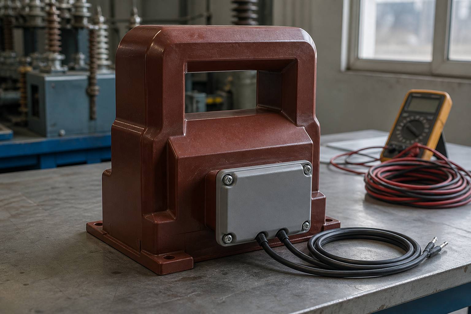
What Makes a Class PX Current Transformer Different?
In a standard protection class, the guarantee is a composite error at a multiple of rated current. A 5P10 CT, for example, is guaranteed to keep its composite error within the limits of the 5P class up to ten times rated current, with a stated burden. The buyer does not need to know anything about the core to select it, and two CTs from different manufacturers that both carry 5P10 are broadly interchangeable for overcurrent duty.
The PX class makes a different promise. It promises that the secondary will produce at least a stated voltage before the core bends over, that the winding resistance will not exceed a stated value, and that the magnetising current at the knee point will not exceed a stated limit. Those three numbers describe the core and the winding directly, which is exactly what a differential or high-impedance scheme needs, because such a scheme balances voltages across the CT secondary circuits rather than relying on a ratio.
The practical consequence is that PX CTs are not interchangeable by label. Two units both marked "PX" can have completely different performance, because the label carries no values on its own. The values are the specification.
Where Does the PX Class Come From?
The designation began as class X in British Standard BS 3938. Technical literature from the instrument-transformer field records that this class specifies the minimum knee-point voltage of the CT, imposes a maximum secondary winding resistance, and sometimes specifies a maximum magnetising current at the knee-point voltage. The same literature notes that the class was to be defined in the IEC framework under the name PX, and PX is the term used in IEC-based project specifications today.
The current international standard for inductive current transformers is IEC 61869-2:2012, which applies to newly manufactured inductive current transformers used with electrical measuring instruments, protective devices, or both. National and utility specifications sit on top of it, and it is those project documents that usually fix the PX parameter values, because the values come from a protection study rather than from a catalogue.
This matters when a buyer asks for "PX CTs" without a study. There is no standard table of PX ratings to choose from. A supplier who offers one without asking for the knee-point voltage, the winding resistance limit and the excitation current limit is guessing, and the guess will normally be either an oversized core that does not fit the panel or an undersized one that saturates in the through-fault.
What Do Vk, Rct and Io Mean?
Three quantities carry the specification, and each has a precise meaning that is easy to blur in conversation.
| Symbol | What it describes | How it is written | |
|---|---|---|---|
| Knee-point voltage | Vk | The secondary voltage at which a small further increase in voltage produces a large increase in excitation current — the point where the core stops behaving linearly | A minimum, for example "Vk not less than" a value set by the protection study |
| Secondary winding resistance | Rct | The DC resistance of the secondary winding itself, which adds to the lead and relay burden and consumes part of the available volts | A maximum, because a higher resistance steals voltage from the scheme |
| Excitation current at Vk | Io | The magnetising current drawn by the core at the knee-point voltage — the current that is not delivered to the burden | A maximum, where the scheme is sensitive to it |
The knee point has a formal definition in this context: the point on the excitation curve at which a 10% increase in voltage produces a 50% increase in magnetising current. That definition is what makes Vk reproducible between a design calculation, a factory test and a site test, and it is the number that should appear in the purchase specification.
There is a subtlety worth understanding, because it explains a common argument between supplier and customer. The knee point is not the saturation point. Protective-relay literature describes the knee point as the point of maximum permeability, located by a 45-degree tangent to the excitation curve, and notes that a CT with a well-defined knee point may still have no discernible saturation point. Saturation, in the ANSI rating tradition, is defined by a ratio correction limit at a stated multiple of rated current rather than by the knee. So a unit can meet its Vk and still saturate during a fault with a heavy DC offset — which is precisely why the PX scheme is designed with a margin rather than to the knee point exactly.
Why Does the Knee Point Matter in a Differential Scheme?
A differential relay compares currents from two or more CTs. For the comparison to mean anything, each CT must reproduce the primary current faithfully during the through-fault, including the DC component that appears when a fault starts at an unfavourable point on the wave.
Reproducing that current requires voltage. The CT must drive the secondary current through its own winding resistance, the lead resistance and the relay burden, and it must do so while the core is still able to change flux. If the required voltage exceeds what the core can support, the core saturates, the secondary current collapses, and the relay sees a difference that is not a fault. The result is a false trip on a healthy feeder, or a delayed operation on a real one.
The PX specification attacks this directly. The study calculates the maximum voltage that will appear across the secondary circuit during the worst through-fault — usually the fault level at the busbar, referred to the secondary, multiplied by the total loop resistance — and adds a margin. That figure becomes the minimum Vk. The maximum Rct then limits how much of that voltage is lost inside the transformer before it reaches the leads, and the maximum Io limits the spill current that the core itself contributes.
Relay application literature makes the matching requirement explicit for differential schemes: where two CTs form a pair, they should have the same excitation curve, with matching knee-point voltage and the same excitation voltage at a stated excitation current. A PX pair quoted as two independent units that each meet a minimum can still be mismatched in practice, because "not less than" permits one unit to be far above the other. If the scheme depends on balance, the enquiry should state a tolerance band or ask for the measured excitation values, not just a pass against the minimum.
How Is a Class PX Specification Written?
The specification is short, but every line has to come from the protection study. A PX clause that a supplier can quote against contains the following.
| Content | Source of the value | |
|---|---|---|
| Ratio | Rated primary and secondary current, and any taps required | Load and fault study |
| Class | PX, with the standard or project specification referenced | Project specification |
| Vk | Minimum knee-point voltage, with the test method stated | Protection study, from the maximum secondary loop voltage |
| Rct | Maximum secondary winding resistance at a stated temperature | Protection study, from allowable voltage loss |
| Io | Maximum excitation current at Vk, where the scheme needs it | Protection study, from allowable spill current |
| Physical | Cores, secondary terminal arrangement, insulation level, indoor or outdoor, mounting | Panel layout and site conditions |
| Evidence | Excitation test record and resistance measurement for the supplied unit, not a type-test summary alone | Routine test requirement |
The last line is where PX procurement most often goes wrong. A type-test report proves that a design can meet a class; it does not prove that the unit in the crate has the knee point the scheme needs. Because PX is defined by measured quantities, the routine test record for the individual unit is the evidence that matters, and it should be a condition of acceptance rather than a document requested after delivery.
How Is a PX Current Transformer Verified?
Verification is an excitation test plus a resistance measurement, and both are routine work in a CT test bay.
- Measure the secondary resistance. A DC resistance measurement across the secondary terminals gives Rct directly. It should be compared with the declared maximum, and corrected to the reference temperature if the specification states one
- Sweep the excitation curve. Apply a variable voltage to the secondary with the primary open, and record current at a series of voltage points up to and beyond the expected knee. The curve is the primary record; the knee point is read from it
- Locate the knee consistently. Apply the definition in the specification — the 10% voltage increase producing a 50% current increase — or the tangent construction the project names. Two different constructions on the same curve can give two different numbers, which is why the method belongs in the specification
- Check Io at Vk. Read the excitation current at the declared knee-point voltage and compare it with the maximum
- Confirm ratio and polarity. These are separate checks and are not implied by the excitation test. The primary injection test guide covers the primary-side verification that follows
- Record the curve, not just the verdict. A pass or fail stamp is not enough for a differential scheme; the commissioning engineer needs the measured curve to compare against the partner CT
PX Versus 5P and 10P: Which Should a Project Use?
The choice follows from the scheme, not from a preference for precision.
| 5P / 10P | PX | |
|---|---|---|
| How performance is stated | Composite error class and accuracy limit factor | Knee-point voltage, maximum Rct, maximum Io |
| Selection effort | Choose class and ALF from a standard table | Calculate from the protection scheme and the secondary loop |
| Interchangeability | Broad, within the same class and ALF | Low; two units both marked PX can differ substantially |
| Typical duty | Overcurrent and earth-fault protection | Differential, high-impedance and other schemes that depend on secondary balance |
| Evidence needed at delivery | Type test and routine test to the class | Individual excitation curve and Rct measurement |
Many MV panels need both. A typical feeder CT has a metering core and a protection core, and the two are specified differently: the metering core follows an accuracy class such as 0.5 or 0.2S, while the protection core may be 5P20 for overcurrent or PX where a differential scheme is involved. The CT accuracy class guide covers the metering and standard protection classes, and the ratio selection guide covers the primary current choice that applies to every core.
Five Mistakes That Recur in PX Enquiries
- Asking for PX without values. The class name alone specifies nothing. Without Vk, Rct and Io there is no technical requirement to quote against
- Quoting Vk without a test definition. The same curve can yield different knee points under different constructions. State the definition with the value
- Ignoring lead resistance. A generous Vk at the terminals can still be insufficient at the relay if the secondary leads are long. The study has to use the loop resistance, not the CT alone
- Mismatching a differential pair. Two CTs that each exceed the minimum Vk can still have different curves. Specify the matching requirement, and ask for both measured curves
- Accepting a type test as unit evidence. A PX acceptance should rest on the excitation record for the delivered unit, because that is what the scheme depends on
Two further points are worth a line in the enquiry even though they are not PX parameters: the short-time withstand current and its duration, which size the primary and the thermal design, and the insulation level for the system voltage. The short-time withstand current guide explains why the duration must be written next to the current, and the medium-voltage CT guide covers the construction choices that sit around the core.
Frequently Asked Questions About PX Protection CTs
What is a class PX current transformer in simple terms?
It is a protection current transformer whose performance is defined by measured secondary quantities — minimum knee-point voltage, maximum winding resistance and maximum excitation current — instead of a standard accuracy class. The values come from the protection study.
What is the difference between class PX and 5P?
A 5P CT is selected from a standard table and guaranteed by a composite error at a multiple of rated current. A PX CT is built to calculated values that describe the core and winding directly. 5P suits overcurrent protection; PX suits schemes that depend on secondary balance, such as differential protection.
What is knee-point voltage on a current transformer?
It is the point on the excitation curve where a 10% increase in applied secondary voltage produces a 50% increase in magnetising current. It marks the end of linear operation for practical purposes, and it is the voltage the PX specification guarantees as a minimum.
Is the knee point the same as saturation?
No. Protective-relay literature describes the knee point as the point of maximum permeability, not the point of saturation, and notes that a CT with a clear knee may have no sharply defined saturation point. Saturation is normally defined by a ratio-correction limit at a stated multiple of rated current.
Why is Rct limited in a PX specification?
Because the secondary winding resistance consumes part of the voltage the core can produce. A high Rct leaves less voltage for the leads and the relay, so the scheme saturates earlier than the knee-point figure suggests. The specification therefore caps Rct rather than leaving it to the manufacturer.
Why specify a maximum excitation current at Vk?
Because excitation current is the part of the secondary current that never reaches the relay. In a scheme that compares currents, that spill current appears as an error. Capping Io at the knee-point voltage limits how much the core itself contributes to the imbalance.
Which standard covers class PX current transformers?
IEC 61869-2:2012 is the current international standard for inductive current transformers used for measurement and protection. The PX class originated as class X in BS 3938, and project specifications normally add the parameter values that the standard itself does not fix.
What evidence should be supplied with a PX current transformer?
The excitation test record and the secondary resistance measurement for the individual unit, plus the ratio and polarity results. A type-test report alone does not demonstrate that the delivered unit meets the calculated knee-point voltage.
Sources and Further Reading
- Electrical Engineering Portal — Learn How To Specify Current Transformers — class X and PX definition, minimum Vk, maximum Rct, magnetising current at Vk and the knee-point definition
- Schweitzer Engineering Laboratories — Current Transformer Concepts — the knee point as maximum permeability, the saturation criterion, and matching of CT pairs for differential schemes
- IEC 61869-2:2012 — Instrument transformers, Part 2: Additional requirements for current transformers — scope of the current international standard
The PX class is best understood as a specification rather than a product category. The supplier's job is to build a core and a winding that meet three measured numbers; the buyer's job is to make sure those numbers came from the scheme, that the test method is defined, and that the delivered unit comes with the curve that proves it.
Nahu Group manufactures current transformers for 10–35 kV distribution, including multi-core units with separate metering and protection cores. If a differential or high-impedance scheme needs a PX core, send the knee-point voltage, the Rct limit and the excitation current requirement and we will confirm the design against the panel dimensions.
Published October 20, 2026 · Nahu Group (NAHU Electric Technology)