
A primary injection test of current transformer circuits is a site test in which a known current is passed through the primary circuit and the secondary output is measured, so that the transformer's real ratio, polarity and secondary loop are proved under the conditions that actually exist on the installation. It is normally carried out at commissioning, and again after a current transformer is replaced or its secondary wiring is disturbed.
The nameplate states what the transformer should do. The primary injection test shows what it does do — through the real primary path, the real terminal blocks, the real test switches and the real burden of the connected relays and meters.
This guide covers what the test proves, how it differs from secondary injection, how it is carried out on window, bar-primary and multi-ratio current transformers, what has to be recorded, and the safety rule that governs the whole procedure.
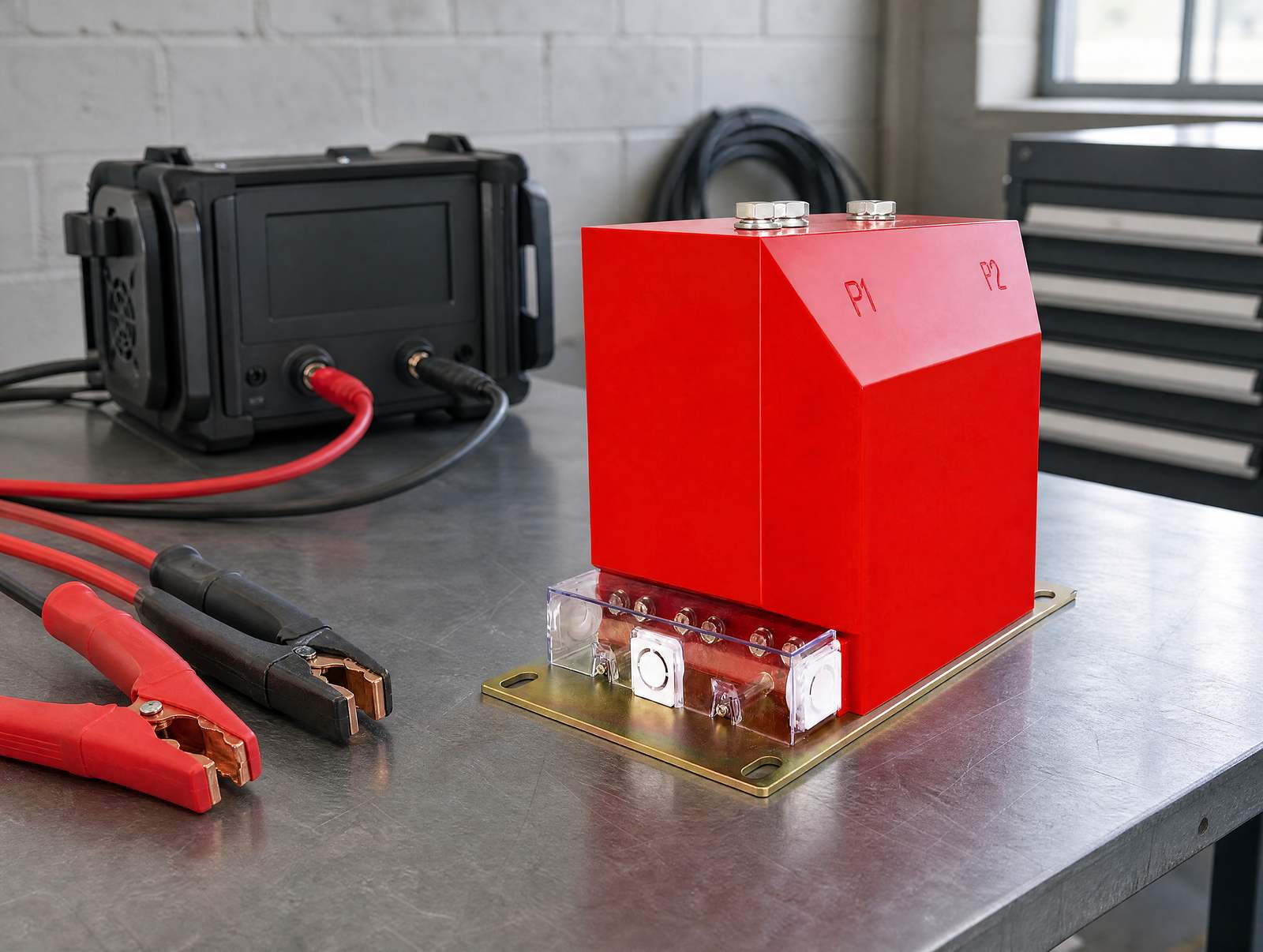
What Is a Primary Injection Test on a Current Transformer?
A current transformer produces a secondary current proportional to the current flowing in its primary circuit. A primary injection test verifies that proportionality on the real installation: current is injected into the primary circuit — through the primary bar, through the busbar, or through a conductor passed through the window — and the resulting secondary current is measured at the secondary terminals.
Because the injected current actually flows in the primary path, the test exercises everything between the current source and the measuring instrument: the primary conductor and its terminations, the transformer itself, the secondary terminals, the secondary cabling, the terminal blocks, any test or shorting switches, and the burden of the devices connected across the secondary.
A ratio printed on a nameplate, a routine test report from the factory and a site test are three different things. The first two describe the unit as manufactured. The site test is the only one that also covers the installation, and that is why primary injection testing belongs to commissioning rather than to factory acceptance. For the wider sequence of checks that surround it, see our instrument transformer site testing checklist; this article deals with the primary injection test itself, in depth.
Primary Injection vs Secondary Injection: What Each One Proves
The two methods are often treated as interchangeable. They are not, and the difference decides how much of the circuit you have actually proved.
| Primary injection test | Secondary injection test | |
|---|---|---|
| Where the current is applied | Into the primary circuit — the primary bar, the busbar, or a conductor passed through the CT window | At the receiving device, typically at its own test terminals |
| What is included in the test | The transformer itself, the secondary wiring, terminal blocks, test switches and the connected burden | The measurement and logic of the receiving device only |
| What it can prove | Effective ratio, polarity, secondary loop continuity and the burden actually present | That the device responds correctly to a given input |
| What it cannot prove | Nothing about the correctness of the protection settings applied to the measured current | That the transformer produces that input, or that the wiring delivers it to the right terminal |
| Typical use | Commissioning, and re-verification after the primary or secondary circuit is disturbed | Routine periodic testing of relays, meters and trip units |
In secondary injection a simulated secondary current is applied at the receiving device. The device's measurement and logic are exercised, but the current sensors, the wiring between them and the device, and the primary current path are all outside the test. That limitation is documented most explicitly for circuit-breaker trip units: TestGuy's comparison of the two methods states that secondary injection “does not verify the current sensors, wiring, or circuit breaker current-carrying components”, and concludes that this is the main reason primary injection is regarded as the stronger method.
The same logic carries across to the secondary loop of a current transformer. Secondary injection confirms that a relay or meter responds to a given input. It does not confirm that the transformer produces that input, that the polarity is correct, or that the wiring delivers it to the intended terminal.
The trade-off is practical rather than technical. Primary injection is slower and needs heavier test equipment, so it is usually reserved for commissioning and for the specific situations listed further down this page. Secondary injection is cheaper and is the sensible choice for routine checks of the receiving devices. A well-constructed programme uses both.
What Does a Primary Injection Test Actually Prove?
It confirms the true ratio against the nameplate
With a known primary current flowing and the secondary output measured, the effective ratio follows directly from the two readings. Comparing that with the marked ratio shows whether the transformer is doing what the nameplate claims, on this installation. TestGuy's guide to the electrical tests performed on current transformers describes the ratio test as injecting a primary current and measuring the current output, or injecting a secondary voltage and measuring the induced primary voltage.
Ratio is not only a manufacturing property. OMICRON's overview of common instrument transformer tests notes that a measured ratio or ratio error that departs from expectation can indicate shorted turns, open windings or manufacturing defects — and on site it can equally indicate a wrong tap, a mis-wired secondary, or a partially shorted secondary loop. A number read off a nameplate cannot separate those cases. A primary injection test can.
It confirms polarity and the phase relationship
Polarity is the relationship between the instantaneous direction of primary current and the direction of secondary current. The markings P1 and P2 on the primary side, and S1 and S2 on the secondary side, define that relationship. Connect the secondary the wrong way round and the magnitude can still look perfect while the phase reference is inverted.
An inverted reference is invisible in a ratio measurement, but not in protection. OMICRON notes that a polarity check prevents faulty measurements, relay misoperation and protection failures, and that it is used to detect wiring errors or reversed connections. A differential or directional scheme fed with an inverted current reference can misoperate in precisely the conditions it was installed to detect.
Polarity is also a site condition as much as a product property. The transformation polarity inside the transformer is fixed at manufacture; whether it survives the terminals, the test switches and the run of cable into the relay is decided by the wiring. Only a test that drives the primary proves the whole path.
It proves the whole secondary loop, not just the transformer
A current transformer only delivers its specified accuracy into a burden within its declared limit. The burden is everything connected across the secondary terminals — relay and meter current coils, terminal blocks, test switches, and the resistance of the secondary cable itself. Our guide to choosing a current transformer ratio covers how that choice is made; the injection test is where it stops being a calculation and becomes a measurement.
TestGuy describes the burden test as injecting the rated secondary current from the CT terminals toward the load side with the CT isolated, then monitoring the voltage drop across the injection points and at points through the circuit, including to ground. An excessive burden produces a secondary current lower than the transformer should deliver for the primary current flowing — an error that no nameplate calculation will predict.
It exposes wiring, terminal and test-switch problems
Because the injection current passes through the physical secondary circuit, the test finds the faults a bench test cannot reach: a conductor landed in the wrong terminal, a shorting link left in place, a test switch that does not close properly, a connection that has corroded since installation. These are installation faults, and installation is exactly what a factory test never touches.
How Is a Primary Injection Test Carried Out?
Test set and injected current
The test set supplies an adjustable current at low voltage into the primary circuit and measures the secondary output. How much current is needed depends on the ratio: a 100/5 transformer needs far less primary current than a 2000/5 unit to produce a readable secondary reading. OMICRON's note on direct testing describes the method as injecting high current or voltage into the primary circuits, and records that it often requires large primary injection equipment. That equipment constraint, more than anything else, is what shapes how the test is planned on site.
Where the rated primary current is high, driving a proportional fraction of it through the primary with portable equipment is not always possible. The usual answer is to increase the number of primary turns the injection current passes through, which raises the ampere-turns applied for the same test current.
Window, bushing and bar-primary current transformers
How the primary current is applied depends on the construction. TestGuy's introduction to current transformer types sets out four typical forms: window, bushing, bar and wound. A window transformer has no primary winding of its own — the primary is the conductor passed through the aperture. Solid-core window types require the primary conductor to be disconnected to fit them; split-core types can be installed without breaking the conductor. A bar-primary transformer has a permanent bar as its primary conductor. Bushing current transformers are window types built around a high-voltage bushing and are usually not directly accessible.
For a window or bushing transformer, the injection conductor is passed through the aperture. Looping that conductor more than once multiplies the ampere-turns applied for the same test current, which is how a modest portable set can simulate a much larger primary current. For a bar-primary or wound transformer the injection current has to be driven through the existing primary path, and the test equipment has to be sized accordingly.
Multi-ratio and multi-core units
Many medium-voltage current transformers offer several ratios by re-linking secondary terminals, and often carry more than one core — typically a metering core and one or more protection cores. Each usable combination is a separate circuit and has to be proved in its own right. Testing one tap proves that tap; it says nothing about the accuracy of another. The same applies to a second core: proving the metering core does not prove the protection core.
What to record
Record the injected primary current, the measured secondary current, the tap or terminal combination under test, the core designation, the burden connected at the time of the test, and the accept or reject decision against the project's criteria. The record matters as much as the test: a commissioning record that names the tap and the core is evidence, while a tick in a box is not.
Which Current Transformers Are Difficult to Primary-Inject in One Pass?
Very high ratios and fixed, inaccessible primaries are the awkward cases. A transformer with a rated primary current far above what portable equipment can supply, and a primary that cannot be looped, has to be tested by another method or with the primary circuit opened to insert turns. Bushing current transformers fall into this category because the primary is the bushing conductor itself.
This is where the comparison with model-based testing becomes relevant. OMICRON distinguishes direct testing, which injects high current or voltage into the primary circuits, from model-based testing, which combines low-level test signals with a mathematical model of the transformer to assess its condition. Both approaches have a place, but they are not the same evidence, and a specification that demands primary injection is asking for the direct method.
Safety: The Open-Secondary Hazard
A current transformer secondary must never be left open while current can flow in the primary. This is the single most important rule in the procedure, and it applies as much to the person holding the test leads as to the transformer.
PowerUC's explanation of why the secondary must not be open sets out the mechanism. With the secondary open there is no secondary current, so the secondary magnetomotive force no longer opposes the primary, the core flux rises sharply, and a very high voltage is induced across the open secondary terminals. The consequences it lists are a risk of electric shock, damage to the transformer insulation, arcing, and permanent damage to the core as it saturates.
TestGuy's current transformer basics page states the working rule directly: a current transformer should remain shorted until it is connected to its secondary circuit, and should always have a burden or load connected when it is not in use, because otherwise a dangerously high secondary voltage can develop across the secondary terminals. In practice that means shorting links and test switches are safety devices, not accessories — and their condition is part of what the test is checking.
Residual magnetism after testing
The same core that makes the open-secondary condition dangerous can also hold magnetisation. OMICRON notes that residual magnetism left in a core after testing or after a grid event shifts the magnetisation curve and can push the transformer into premature saturation, distorting both measurement and protection performance, and that proper assessment and demagnetisation are essential. TestGuy's description of the excitation test sequence — raising voltage in steps and returning it gradually to zero — reflects the same concern. Demagnetise at the end of a primary injection test using the procedure given for the test set in use.
When Should a Primary Injection Test Be Repeated?
OMICRON's guidance on testing frequency makes the point that intervals depend on the transformer type, its criticality and its environment, and distinguishes commissioning tests, periodic maintenance inspections and post-fault diagnostics. Repeating the primary injection test is warranted whenever the circuit it proves has been disturbed:
- At commissioning, before the protection is placed in service
- After a current transformer is replaced or its ratio links are changed
- After the secondary wiring, terminal blocks or test switches have been worked on
- After a fault or a protection operation whose cause is not established
- While investigating a metering or protection discrepancy
For everything else, follow the periodic interval set by the project's test plan and the operator's own standards. A test that is repeated on a schedule somebody invented is worth less than one repeated whenever the circuit changes.
Which Standards Apply?
The international framework for instrument transformers is the IEC 61869 family. As set out in this overview of the IEC 61869 standards, Part 1 carries the general requirements for instrument transformers with a nominal voltage above 1 kV AC or 1.5 kV DC, and Part 2 covers inductive current transformers specifically. Further parts address voltage transformers, combined transformers, capacitor voltage transformers, digital interfaces, low-power instrument transformers and DC applications. The earlier IEC 60044 series was the predecessor.
Two practical points follow. First, a purchase specification that says only “IEC 61869 compliant” is not yet a specification: ask which part and which edition, and which ratio, accuracy class, rated burden and output are actually being bought. Second, a site test is not a type test. Type and routine tests demonstrate that a design and a unit meet a standard; a primary injection test demonstrates that this installation is wired and burdened correctly. One cannot substitute for the other.
Frequently Asked Questions
What is the difference between a primary injection test and a ratio test?
A ratio test is one measurement. A primary injection test is the procedure that delivers it, and it normally also establishes polarity and the condition of the secondary loop in the same session. Ratio, polarity and burden are separate checks, and a primary injection test is the practical way to make all three on site.
Can a primary injection test replace secondary injection testing?
No, and it is not meant to. Primary injection proves the transformer and its secondary circuit up to the receiving device. Secondary injection proves the behaviour of the receiving device against a known input. Commissioning normally calls for both, because each covers what the other cannot.
Why can't the secondary of a current transformer be left open?
With an open secondary there is no opposing secondary magnetomotive force, so the core flux rises sharply and a very high voltage is induced across the open terminals. That creates a shock hazard, can break down the insulation, and can permanently damage the core. Keep the secondary shorted or burdened whenever primary current can flow.
How much current is needed for a primary injection test?
It depends on the ratio and on what has to be readable at the secondary. The aim is a primary current that produces a clear, measurable secondary output within the range of the test instruments. Where the ratio is high and the primary cannot be looped, verify the required primary current against the test set's output capability before planning the job.
Do I need to demagnetise the CT after testing?
Residual magnetism shifts the magnetisation curve and can cause premature saturation, so demagnetisation after a test that has driven the core into saturation is standard practice. Use the procedure specified for the test set in use rather than assuming the core is clean.
Can a window-type CT be primary-injected without disconnecting the primary?
It depends on the core construction. A split-core window transformer can be fitted around a conductor without breaking it; a solid-core window transformer requires the primary conductor to be disconnected to fit it in the first place. Since the primary conductor is the primary winding, the injection conductor in a window transformer is simply passed through the aperture — or looped through it more than once to raise the ampere-turns.
Is insulation resistance testing part of the same procedure?
No, it is a separate check. TestGuy lists six electrical tests that are typically performed on current transformers — ratio, polarity, excitation (saturation), insulation resistance, winding resistance and burden — and they are distinct measurements with distinct test equipment. A primary injection test addresses ratio, polarity and burden; insulation resistance and winding resistance are separate tests.
Sources and Further Reading
- OMICRON — Common electrical tests on instrument transformers — ratio and ratio error, polarity, burden, and the effects of residual magnetism
- PowerUC — Why the current transformer secondary should not be open — the mechanism, the voltage, and the damage it causes
- TestGuy — 6 electrical tests for current transformers explained — ratio, polarity, excitation, insulation resistance, winding resistance and burden testing
- TestGuy — Primary vs. secondary injection testing — what each method includes and excludes, written for circuit-breaker trip units
- TestGuy — Current transformer basics: ratio, polarity and class — CT types, polarity markings, and the rule that a CT must never be left open
- IEC 61869 instrument transformer standards — an overview — the current structure of the IEC 61869 family and its parts
A primary injection test is the point at which the paper design of a current transformer circuit meets the installation. Ratio, polarity and burden are all settled by the same procedure, on the real primary path and through the real secondary wiring, and the open-secondary rule applies from the first connection to the last. Done properly, and recorded properly, it is the strongest single piece of evidence that a metering or protection circuit will behave as designed when it matters.
Nahu Group manufactures 10–35 kV current transformers and voltage transformers with the ratio, accuracy class and core configuration a project's primary injection test is meant to confirm, and supplies the routine test documentation that accompanies them. Browse the current transformer range, or talk to the engineering team about the taps, cores and burdens your scheme uses.
Published October 13, 2026 · Nahu Group (NAHU Electric Technology)