
Rated short-time withstand current (Icw or Ik) is the r.m.s. value of fault current that switchgear can carry in the closed position for a stated time without damage. Rated peak withstand current (Ipk or Ip) is the peak value of the first major loop of that current, which the equipment must survive without mechanical deformation. The two numbers describe the same fault event from two angles: one thermal, one electrodynamic.
Together with the rated duration of short circuit, they define what a switchgear assembly can survive while waiting for protection to clear a fault. They are the ratings most often copied into a tender without being understood, and the ones most often compared incorrectly between a circuit breaker and the enclosure it sits in.
This guide explains both ratings as they are defined in IEC 62271-1, why the peak value is a multiple of the r.m.s. value rather than an independent measurement, how the standard values are chosen, and what to check on a nameplate or a type-test certificate before accepting a quotation.
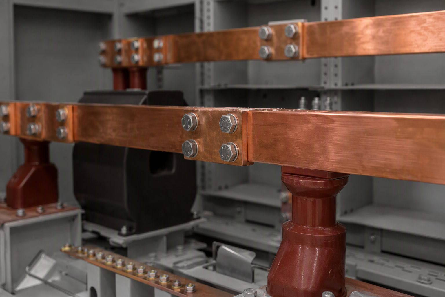
What Does Short-Time Withstand Current Mean?
IEC 62271-1 defines Ik as the r.m.s. value of the current which the switchgear and controlgear can carry in the closed position during a specified short time under prescribed conditions of use and behaviour. Three parts of that sentence carry the meaning.
Closed position. The rating is about carrying current, not about interrupting it. A circuit breaker's ability to break a fault is a separate rating. The withstand current describes the period between fault inception and the opening of the contacts, when the equipment is still carrying the full fault current.
Specified short time. The rating has no meaning without its duration. IEC 62271-1 sets the standard value of rated duration of short circuit at 1 s, and states that where a different duration is needed the recommended values are 0.5 s, 2 s and 3 s. A rating of 25 kA for 1 s and a rating of 25 kA for 3 s are not the same equipment.
R.m.s. value. The number is an r.m.s. current, which is what makes it a thermal rating. The heating produced in a conductor depends on the square of the current and on how long it flows; that is why the duration is part of the rating rather than a separate test condition.
The thermal duty is straightforward to picture: the busbar, contacts and connections are designed to absorb a defined quantity of energy before protection operates. If the actual clearing time is longer than the rated duration, the equipment may still be intact electrically and yet have been overheated beyond its design.
What Is Rated Peak Withstand Current?
IEC 62271-1 defines the rated peak withstand current as the peak current associated with the first major loop of Ik which switchgear and controlgear can carry in the closed position. Where the short-time rating is a heating question, the peak rating is a force question.
The forces between parallel conductors carrying fault current scale with the square of the instantaneous current. At the peak of the first loop, those forces reach their maximum, and they act on busbars, supports, insulators, current transformer bars and the enclosure itself. A busbar system that passes the thermal test but is under-braced mechanically will bend, distort or tear free at the peak, even though the energy absorbed was within the thermal rating.
This is why the peak rating is often the one that decides the physical design of a compartment. Adding copper increases the thermal margin; adding supports and increasing creepage distances increases the mechanical margin. The two are related but not interchangeable.
Why Is the Peak Withstand Current 2.5 Times the Short-Time Current?
A fault current is not a symmetrical sine wave at the instant it starts. It contains a decaying d.c. component, which offsets the first few cycles and pushes the first peak above the value that the r.m.s. symmetrical current alone would suggest. The magnitude of that offset depends on the point on the voltage wave at which the fault occurs and on the ratio of reactance to resistance in the system — expressed in the standards as a d.c. time constant.
IEC 62271-1 ties the rated peak withstand current to that time constant rather than fixing a single multiplier. A d.c. time constant of 45 ms covers the majority of cases and corresponds to a rated peak withstand current equal to 2.5 times Ik at a rated frequency of 50 Hz and below, and 2.6 times at 60 Hz. For systems where the time constant is higher — the standard names 60 ms, 75 ms and 120 ms as generally suitable values — the preferred value is 2.7 times Ik.
The same relationship appears in application guidance. The Electrical Installation Guide states the peak relationship as Ip = 2.5 × Is for a 50 Hz supply with a 45 ms d.c. time constant, and Ip = 2.6 × Is for 60 Hz, where Is is the r.m.s. symmetrical fault current with no d.c. component.
Two consequences follow. First, a peak rating is not something a manufacturer chooses freely; it follows from the short-time rating and the assumed time constant. Second, comparing a 50 Hz peak rating with a 60 Hz peak rating without adjusting the multiplier overstates or understates the margin by about four percent, which is enough to matter at the top of a range.
| Rating | What it defines | Duty | |
|---|---|---|---|
| Ur | Rated voltage | Maximum r.m.s. voltage the equipment can withstand permanently | Insulation coordination |
| Ir | Rated normal current | R.m.s. current the equipment can carry continuously within its temperature-rise limits | Continuous thermal |
| Ik (Icw) | Rated short-time withstand current | R.m.s. fault current carried in the closed position for the rated duration | Short-time thermal |
| Ip (Ipk) | Rated peak withstand current | Peak of the first major loop that the equipment can carry | Electrodynamic |
| tk | Rated duration of short circuit | Time for which Ik can be carried | Thermal time base |
| Isc | Rated short-circuit breaking current | R.m.s. symmetrical current the breaker can interrupt | Interruption |
Which Standard Values Are Available?
IEC 62271-1 requires the standard value of Ik to be selected from the R10 series of IEC 60059. The standard reproduces that series as 1, 1.25, 1.6, 2, 2.5, 3.15, 4, 5, 6.3 and 8, and their products by powers of ten. In medium-voltage practice this produces the familiar ladder of 12.5, 16, 20, 25, 31.5, 40 and 50 kA.
Because the series is logarithmic rather than linear, the step between adjacent ratings is roughly 25 percent. A specification that asks for 30 kA is therefore not a standard value; it will either be met by a 31.5 kA design or require a non-standard declaration, and both outcomes should be stated explicitly rather than assumed.
Durations follow the same discipline. One second is the standard value, with 0.5 s, 2 s and 3 s as the recommended alternatives. Where a project specifies 3 s because of slow upstream protection, the equipment is being asked for three times the thermal energy of a 1 s rating at the same current, which is a substantially different design requirement rather than a paperwork preference.
Rated Making Current and Peak Withstand Current: Why They Differ
A circuit breaker carries a rated short-circuit making current as well as a peak withstand current, and on a test report the two numbers are sometimes different. That is not automatically an error.
The making current describes the peak current the breaker can close against — a duty imposed on the contacts and the operating mechanism when the breaker is closed onto an existing fault. The peak withstand current describes the peak current the complete assembly can carry while already closed, which loads the busbars, supports and enclosure. The two ratings come from different standards: IEC 62271-100 covers high-voltage alternating-current circuit breakers, while IEC 62271-200 covers alternating-current metal-enclosed switchgear and controlgear assemblies.
Because the test objects differ, the numbers can legitimately differ. A breaker may be rated to make a lower peak than the assembly it is installed in can withstand, since the assembly's busbar system can be braced more heavily than the breaker's contacts can be asked to close onto repeatedly. When a report shows a making current below the peak withstand current, the correct response is to identify which rating belongs to which object, not to assume a typographical error.
The practical rule for a buyer is to keep the two questions separate. Ask for the breaker's making current and breaking current as breaker ratings. Ask for the assembly's short-time and peak withstand ratings as assembly ratings. A quotation that mixes them is not comparable with one that does not.
How Do You Check a Rating Against the Fault Level?
A rating is only adequate relative to a calculated fault level at the point of installation. Three checks cover the thermal, dynamic and interruption duties:
- Thermal. The rated Ik must exceed the r.m.s. symmetrical fault current at the installation point, and the rated duration must exceed the time protection takes to clear the fault.
- Dynamic. The rated peak withstand current must exceed the peak asymmetrical fault current at the installation point — the value that includes the d.c. offset, not the symmetrical r.m.s. figure.
- Interruption. The breaker's rated short-circuit breaking current must exceed the fault current it is expected to interrupt at its rated voltage.
The d.c. time constant used in the fault study should match the assumption behind the equipment rating. If the system has a higher X/R ratio than the 45 ms case, the actual peak can exceed 2.5 times the symmetrical current, and an assembly rated on the standard multiplier may be under-dimensioned even though its nameplate looks adequate. This is a system-study question, not a catalogue question, and it should be answered before the switchgear is ordered rather than after the fault study is revised.
What Should Appear on the Nameplate and Certificate?
IEC 62271-1 requires ratings to be marked, and a type-test certificate should let a reviewer connect each rating to the test that demonstrated it. In practice, check that the following are present and consistent:
- Ik with its duration stated explicitly — for example 25 kA / 1 s, not 25 kA alone
- Rated peak withstand current, stated as a peak value
- Rated normal current and rated voltage
- The standard and edition against which the equipment was tested
- Reference to the type-test report and the testing station
- The rated frequency, because the peak multiplier depends on it
A nameplate that shows a short-time current without a duration, or a peak value without a frequency, is incomplete. Those omissions are common in abbreviated quotations and rare in full type-test documentation, which is one reason to ask for the certificate rather than the datasheet.
What Are the Common Specification Mistakes?
Five errors account for most of the confusion seen in medium-voltage tenders:
- Quoting breaking current as withstand current. The ability to interrupt a fault and the ability to carry it for a time are different ratings, tested differently.
- Omitting the duration. A short-time rating without a time cannot be compared with a fault clearing time, and therefore cannot be verified.
- Applying a 2.5 multiplier to a 60 Hz system. The standard value at 60 Hz with a 45 ms time constant is 2.6 times, not 2.5.
- Mixing breaker and assembly ratings. A making current from a breaker certificate does not describe the enclosure, and an enclosure peak rating does not describe the breaker's closing duty.
- Assuming the fault level is fixed. Network reinforcement upstream raises the fault level at existing switchboards; a rating adequate at commissioning can become inadequate after a substation upgrade.
How Nahu Group Rates Its Medium-Voltage Equipment
Nahu Group manufactures vacuum circuit breakers, ring main units, load break switches, earthing switches, current and voltage transformers and cable branch boxes for distribution networks. Ratings are declared per unit and supported by test documentation, so that a specification can be checked against a certificate rather than against a brochure.
For buyers comparing configurations, the 11 kV vacuum circuit breaker specification guide sets out how the ratings combine in practice, and the type test report guide explains how to read the evidence behind them. The vacuum circuit breaker range lists the configurations available.
Frequently Asked Questions About Withstand Ratings
What is short-time withstand current?
It is the r.m.s. value of fault current that switchgear can carry in the closed position for a stated time without damage. IEC 62271-1 sets the standard duration at 1 second, with 0.5, 2 and 3 seconds as recommended alternatives.
What is the difference between Icw and Ipk?
Icw is an r.m.s. current that defines the thermal duty. Ipk is the peak of the first major loop of that current and defines the electrodynamic duty on busbars, supports and the enclosure.
Why is peak withstand current 2.5 times the short-time current?
The d.c. component of a fault current offsets the first cycles. With a 45 ms d.c. time constant, IEC 62271-1 gives a peak equal to 2.5 times the short-time current at 50 Hz and 2.6 times at 60 Hz. Higher time constants use a preferred value of 2.7 times.
What is the standard duration of short-time withstand current?
One second is the standard value. IEC 62271-1 states that where a different duration is necessary, the recommended values are 0.5, 2 and 3 seconds.
Is 25 kA for 1 second the same as 25 kA for 3 seconds?
No. The thermal energy absorbed scales with current squared multiplied by time, so a 3 second rating at the same current represents three times the energy of a 1 second rating. It is a different design requirement.
What is the difference between rated making current and peak withstand current?
Making current describes the peak the breaker can close against, loading its contacts and mechanism. Peak withstand current describes the peak the complete assembly can carry while already closed, loading busbars, supports and enclosure. They come from different standards and can legitimately differ.
How do I check whether a switchgear rating is adequate for my fault level?
Compare the rated short-time withstand current with the r.m.s. symmetrical fault current and its duration with the protection clearing time; compare the rated peak withstand current with the peak asymmetrical fault current; and compare the breaker breaking current with the fault current it must interrupt.
Does a higher short-time rating always mean better equipment?
Not on its own. A rating is only meaningful with its duration and with the standard it was tested to. Equipment with a higher current but a shorter duration can absorb less energy than equipment with a lower current and a longer duration.
Sources and Further Reading
- IS/IEC 62271-1:2007 — clauses 4.5, 4.6 and 4.7: rated short-time withstand current, rated peak withstand current and rated duration of short circuit
- Electrical Installation Guide — medium voltages and current values according to IEC standards — definitions of Ir, Ik and Ip
- Electrical Engineering Portal — operational ratings of medium-voltage switchgear — peak relationships at 50 Hz and 60 Hz and the rating set
- Industrial Monitor Direct — rated short-circuit making current versus peak withstand current — why breaker and assembly ratings can legitimately differ
Published October 19, 2026 · Nahu Group (NAHU Electric Technology)