
Busbar temperature monitoring in switchgear is the continuous measurement of temperature at the current-carrying joints inside a switchboard — the bolted busbar splices, the circuit-breaker stabs and the cable lugs — so that a joint which is slowly losing contact pressure is found while it is still a maintenance item rather than an arc fault. The busbar itself is rarely the problem: bars are sized with thermal margin. The joint is where switchgear fails, and inside a closed metal enclosure no ordinary inspection can see it.
That explains why busbar temperature monitoring has moved from a niche retrofit to a standing line item on utility specifications. A bolted connection that loses torque, collects an oxide layer or loosens under vibration does not fail suddenly: its resistance rises, its temperature follows, and the heat accelerates the very degradation that created it.
This guide covers what busbar temperature monitoring measures, why joints overheat, which limits actually apply to a bolted connection, and what a buyer should require at the specification stage.
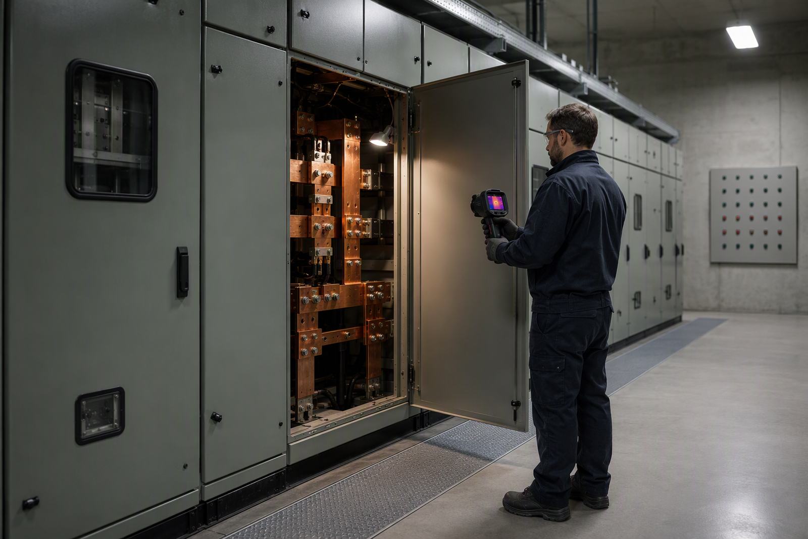
What Is Busbar Temperature Monitoring in Switchgear?
Busbar temperature monitoring is the permanent, automated measurement of temperature at the connection points inside medium-voltage and low-voltage switchgear, reported continuously to an alarm platform instead of being sampled during an occasional site visit.
A complete system has four parts, and it is worth knowing them because suppliers quote them separately:
- Sensors on or against the connection being watched — a busbar splice, a breaker contact, a cable lug, a bushing terminal
- A data acquisition unit inside the panel that interrogates the sensors and converts their readings into temperatures
- Threshold or trend logic, so a reading that is normal at light load but wrong at full load produces an alarm
- A communication path up to SCADA or a building management system
The distinction that matters is between monitoring and surveying. A thermal survey is a snapshot on the day it is taken; busbar temperature monitoring produces a trend line that also exists every other day — continuous, real-time measurement without a panel shutdown or manual inspection.
Why Do Busbar Joints Run Hot?
Overheating at a connection is self-reinforcing. Because heat in a joint rises with the square of the current, a small increase in contact resistance produces a disproportionate rise in local temperature, which then attacks the contact surface further. The mechanisms that start it are well documented.
Loose or incorrectly torqued bolted joints
A bolted busbar joint depends on contact pressure. Under-torque it at installation, or let it relax over years of thermal cycling, and the real contact area shrinks. A Schneider Electric white paper on continuous thermal monitoring identifies cable, busbar and withdrawable circuit-breaker connections as the parts that deteriorate from improper tightening torque or from constant vibration, and cites a National Electrical Testing Association figure that approximately 25 per cent of all major electrical failures are attributed by one major insurance carrier to loose or faulty connections.
Oxidation, corrosion and the wrong contact material
Even at correct torque, a joint degrades chemically. Oxide layers are markedly more resistive than the bare metal beneath them, which is why surface preparation is not cosmetic. IEC TR 60943 — the IEC guidance document on permissible temperature rise for parts of electrical equipment, particularly terminals — states that bare copper tends to deteriorate considerably with time and temperature and that it is unwise to exceed 60 °C to 85 °C. On the same reference ambient of 40 °C, that corresponds to a temperature rise of roughly 20 K to 45 K, which is far below many of the limit values quoted for switchgear assemblies.
The material choice is quantifiable. The same guidance reports aged contact resistance after 1 000 hours in ambient air at a contact force of 10 N: bare copper 20 mΩ, nickel-plated copper 25 mΩ, tinned copper 68 mΩ, and silver-plated copper 0.3 mΩ. Silver ages slowly except in sulphurous atmospheres — a relevant caveat in industrial and coastal locations. Aluminium cannot be used as a contact surface unless its insulating alumina layer is removed by brushing with grease or an equivalent treatment. Tinned contacts bolted and subject to vibration can suffer fretting corrosion, which destroys the plating and with it the joint.
Thermal cycling, vibration and switching
The same white paper identifies two conditions that make all of the above worse. Frequent temperature cycling — the swing between cool nights and hot days, or between low and high load — repeatedly tightens and slackens a joint and contributes to loosening. Frequent on/off switching imposes an electromagnetic shock on the busbar and its connection points that can work them loose as well. This is why the highest-risk installations are not the ones with the heaviest steady load, but the ones that cycle hardest.
Maintenance itself is a recognised cause. Dismantling cables for insulation testing and reassembling them with old grease left in place, incorrect tightening torque, or a contact washer in the wrong position all appear in the recorded failure patterns, as do withdrawable breakers racked in with misaligned clamps.
Overload, harmonics and contamination
Sustained overcurrent raises every joint towards its limit, and harmonic current from variable-frequency drives, UPS systems and other non-linear loads heats a busbar more than the ammeter reading suggests. Conductive contamination inside the enclosure — dust, moisture, carbon tracking — adds leakage paths that heat the conductor locally. None of these produce an obvious external symptom on a closed panel.
What Temperature-Rise Limits Apply to Switchgear Busbars?
This question is often answered loosely, so it is worth being precise about which document says what. Switchgear temperature limits are expressed as a rise above a reference ambient, not as an absolute temperature, and the reference ambient in the standards is 40 °C. A limit quoted as “105” therefore means 105 K of rise, not 105 °C of operating temperature.
| Applies to | What it says about the connection | |
|---|---|---|
| IEC 62271-1 | High-voltage switchgear and controlgear — common specifications | For a bolted connection in air, a limit of 60 K rise for bare copper, bare copper alloy or bare aluminium alloy, and 75 K where the contact is silver- or nickel-coated |
| IEC 61439-1 | Low-voltage switchgear and controlgear assemblies | Lists 70 K for terminals for external insulated conductors; note g to the table states a maximum temperature rise of 105 K for bare copper busbars and conductors |
| IEC TR 60943 | Guidance on permissible temperature rise for equipment parts, in particular terminals | Bare copper deteriorates considerably with time and temperature; advises against exceeding 60 °C to 85 °C |
| Temperature rise test conditions | Verification testing | The average ambient temperature for the duration of the temperature-rise test is not to exceed 35 °C |
Two points follow. First, the limits are not a design target; they are the maximum a design may reach, and components that operate close to them age faster. Second, the standards do not agree as neatly as a specification writer would like. Sergio Feitoza Costa, who chaired IEC Technical Committee 32 when IEC 60943 was first published, argues in a comparative analysis that IEC 61439-1's Table 6 is unclear and that its 105 K allowance for bare copper sits badly against IEC 62271-1's 60 K for a bare bolted connection, and that the applicable limit is the lower of the two.
If your specification quotes a temperature-rise figure, name the document and the edition it comes from. Where the connection is between a busbar and a component such as a circuit breaker, the controlling figure is the lower of the two, not the more convenient one.
Why Can't Infrared Thermography See Inside a Switchgear Panel?
Infrared thermography works on line-of-sight: it reads radiant heat reaching the lens, and a closed steel enclosure blocks it. A survey team can read busbar temperatures through an infrared window in a panel cover, but a window covers one compartment and one angle, not the splice joints behind a barrier.
Scheduled surveys also carry two structural limitations. They are periodic, so a joint that deteriorates between two annual visits is simply not observed; and to be meaningful the panel usually has to be carrying enough load at the moment of the survey to make the joint hot — a fault that only shows at full load is invisible at 30 per cent load. Continuous monitoring avoids all three constraints, and the published comparison between the two methods comes out consistently in favour of permanent sensors for enclosed equipment, with thermography retained for open connections and overhead equipment.
Scheduled inspection is not pointless — its role changes to a periodic cross-check of the monitoring system.
How Do You Monitor Busbar Temperature in Practice?
Two sensor families carry almost all permanent busbar temperature monitoring, and they differ mainly in how the signal leaves a live conductor.
| How it senses | Where it fits | Main limitation | |
|---|---|---|---|
| Fibre-optic sensors | A temperature-sensitive element at the tip of a dielectric optical fibre; the reading is carried as light, not as an electrical signal | Enclosed medium-voltage compartments and any point where an electrically conductive sensor would be unacceptable | Fibre routing has to be planned into the panel, so retrofit is more intrusive than a wireless sensor |
| Wireless sensors | A self-contained sensor clamped to the busbar or bolted connection, transmitting by radio to a receiver in or near the panel | Fast retrofit on existing switchboards; panels with no practical cable route | Metal enclosures attenuate radio signals, so gateway or repeater placement matters; non-harvesting units need battery management |
| Infrared thermography | Handheld or fixed camera reading radiated heat | Open busbar, transformer terminations, overhead equipment; periodic cross-checks through IR windows | Cannot read through a closed metal enclosure; periodic only; needs load present at the time of the survey |
The engineering reason fibre optics dominate enclosed medium-voltage applications is not accuracy alone. A fibre sensor contains no electrical conductor at the sensing point, so it needs no insulation coordination with the conductor it measures and is unaffected by the magnetic field around a busbar carrying thousands of amperes. Published specification for these products typically quotes accuracy of around ±0.5 °C and multi-channel processors serving many sensors from one unit. Wireless sensors trade that immunity for speed of installation — vendor guidance puts a retrofit at roughly 15 to 30 minutes per panel — and some designs harvest their own power from the magnetic field of the busbar they are clamped to.
Where should the sensors be placed?
Sensor count is a design decision, and it should follow consequence rather than symmetry. The points that appear repeatedly in switching-failure analysis are:
- Main busbar section joints — the bolted splices between panels, carrying full bus current and the most thermal cycling
- Circuit-breaker upper and lower contacts — the plug-in or drawout stabs, where racking damage also shows up
- Cable lug terminations — incoming and outgoing lugs, where cable load and dissimilar-metal contact work against the joint
- Bushing and support-insulator terminals — they catch corona-induced heating on medium-voltage assemblies
- Disconnect and earthing-switch contacts — especially where silver plating has worn through
- Instrument-transformer secondary terminals — an open secondary circuit concentrates energy here and shows as abnormal temperature
A system that watches only the busbar splices will miss the breaker contacts, and vice versa: compare the monitored point list, not the channel count.
How Is Temperature Rise Verified Before a Panel Leaves the Factory?
Monitoring comes after the panel is in service. Before that, temperature rise is a design-verification obligation inside a framework most buyers never see. IEC 61439-1, the general rules for low-voltage assemblies, replaced IEC 60439 and introduced three verification methods treated as equivalent: by testing, by calculation or measurement, and by application of design rules. It also removed the old distinction between type-tested and partially type-tested assemblies.
Each method has boundaries. For a multiple-compartment assembly, verification of temperature rise by calculation is permitted only up to a rated current of 1600 A. Where a design is verified by design rules against a similar tested assembly, the rules are strict: the construction type must match, overall dimensions must be the same or larger, and internal separation, power losses and the number of outgoing circuits per section must be the same or less. Engineering guidance points the same way — power-loss calculation and enclosure heat-dissipation analysis at the lower ratings, more advanced thermal modelling as current rises, and full testing typically required above 1600 A.
Temperature rise is not verified in isolation. The same framework covers short-circuit withstand, dielectric properties and the rated diversity factor, and the assembly-level tests around it include resistance to corrosion — six 24-hour damp-heat cycles at 40 ± 3 °C and 95 per cent relative humidity, plus two salt-mist cycles at 35 ± 2 °C — and thermal stability of the enclosure. Degree-of-protection tests belong to the same framework: the IPX1 to IPX6 water tests are deemed a failure if water reaches electrical equipment inside the enclosure.
For a buyer, the practical translation is simple: ask for the design-verification route used, the current at which the assembly was verified, and the ambient temperature assumed. A temperature-rise claim without those three facts is not evidence of anything. If you are specifying medium-voltage equipment, the 11 kV VCB specification guide covers what a switchgear specification should state, and the metal-enclosed switchgear guide covers how enclosure families and separation forms differ.
What Should You Ask For When Specifying Switchgear?
Whether or not monitoring is in scope, these items decide whether a busbar problem is found before it becomes an incident:
- A named design-verification route and its limits. Which method was used, at what rated current, at what ambient.
- A joint specification, not just a busbar specification. Contact surface treatment, plating, hardware grade and the torque-verification record.
- A monitored point list. Which connections carry sensors, and how that list was derived.
- Load-aware alarm logic. A fixed threshold either misses a fault at part load or alarms on a healthy, heavily loaded panel.
- A stated communication protocol. Modbus RTU or TCP, IEC 61850, DNP3 or BACnet — plus hardwired alarm contacts independent of the network.
- The expected service conditions, in writing. Maximum ambient, pollution level, altitude, and whether the site is coastal or industrial.
- A torque-check interval in the maintenance manual. Connections made on site are the most failure-prone, so the manual should say when they are re-checked.
Busbar Temperature in Gulf and Central Asian Installations
The 40 °C reference ambient behind every temperature-rise figure in the standards is not the air temperature in a Gulf switchroom in August, or in a containerised substation in Central Asia. It is a reference condition for testing, and it assumes the assembly is indoors at a typical design range of about −5 °C to +40 °C, with relative humidity up to 90 per cent and altitude below 2 000 m. Outside those conditions the design should be re-checked rather than assumed.
Local conditions push in several directions at once. A higher room ambient reduces the thermal headroom between a healthy busbar and its permitted rise, so a joint that sits comfortably within limits in a temperate plant can sit near them by default. Coastal and industrial atmospheres accelerate the surface oxidation that raises joint resistance — which is why the assembly test framework includes salt-mist and damp-heat cycles. Where drives, rectifiers or UPS systems are added, harmonic current also adds heating that the ammeter does not show.
Nahu Group manufactures current transformers, voltage transformers, metering units and 10–35 kV distribution equipment, including the switchgear cabinets, load break switches and ring main units on the load side of these concerns. For projects that specify thermal verification, the engineering team can confirm which configuration and rating applies. Related reading includes the ring main unit single line diagram explained for how metering, earthing and protection points are arranged inside a cabinet, and the vacuum circuit breaker testing procedure for the commissioning checks that cover the breaker connections.
Frequently Asked Questions
What is busbar temperature monitoring in simple terms?
It is the permanent measurement of temperature at the joints inside a switchboard — the bolted busbar splices, breaker contacts and cable lugs — with the readings reported continuously to an alarm system. Instead of a technician taking a snapshot once a year, the panel reports its own connection temperatures all the time.
Why do busbars overheat at the joints rather than in the middle?
A busbar is sized with thermal margin, but a joint depends on contact pressure and surface condition. Lose torque, gain an oxide layer or introduce vibration, and the contact resistance at that point rises. Because heat rises with the square of the current, a modest rise in resistance produces a much larger rise in local temperature — and the heat then degrades the joint further.
Can thermal imaging detect a hot busbar inside a closed switchgear panel?
No. Infrared thermography needs line of sight, and a closed metal enclosure blocks the radiation. An infrared window can read one compartment from one angle, but it cannot see joints behind a barrier. For enclosed equipment, permanently installed sensors are the reliable method, with periodic thermography kept as a cross-check.
What temperature rise is acceptable for a switchgear busbar?
It depends on the document and the joint. IEC 62271-1 gives 60 K rise for a bare bolted connection in air and 75 K where the contact is silver- or nickel-coated. IEC 61439-1 lists 70 K for terminals for external insulated conductors, with note g stating a maximum temperature rise of 105 K for bare copper busbars and conductors. IEC TR 60943 advises against exceeding 60 °C to 85 °C for bare copper. All of these are rises above a 40 °C reference ambient, and where a busbar meets a component, the lower of the two limits applies.
How often should busbar temperature be checked?
If the equipment matters, continuously rather than periodically. Insurers and standards bodies commonly require annual thermal surveys, and NFPA 70B is one example of a thermal-inspection standard in the United States, but a survey only sees the panel on the day it is taken and only if sufficient load is flowing at that moment. Continuous monitoring has no such gap.
Are wireless sensors as good as fibre-optic sensors for switchgear?
They answer different constraints. Fibre-optic sensors contain no electrical conductor at the measuring point, so they need no insulation coordination with the live busbar and are immune to the magnetic field around it, which is why they are preferred inside enclosed medium-voltage compartments. Wireless sensors install faster and suit retrofit, but metal enclosures attenuate radio signals and non-harvesting designs need battery management.
Does busbar temperature monitoring require an outage to install?
Not necessarily, but it depends on the design and the site rules. Some sensor types can be mounted on an energised connection using approved work procedures and PPE, and retrofit guidance for wireless units describes a brief scheduled outage per panel. Any such work should follow the site's live-working rules and the equipment manufacturer's instructions.
What causes a busbar joint to overheat in the first place?
The recurring causes are under-torqued or relaxed bolted connections, oxidation and corrosion of the contact surface, vibration and repeated thermal cycling, sustained overcurrent or harmonic current, and poor initial assembly quality such as inadequate surface preparation, missing antioxidant compound or unverified torque. Connections made on site are the most exposed.
Sources and Further Reading
- Schneider Electric — Beyond IR thermography: how continuous thermal monitoring improves safety, uptime, and equipment protection (white paper, 2021) — connection deterioration, temperature cycling and the insurance-industry failure statistics
- COGNITOR — IEC 61439-1 temperature rise limits, with the IEC 62271-1 Table 14 and IEC TR 60943 comparison — the quoted limit values and aged contact-resistance data
- Electrical Engineering Portal — IEC 61439 standard for low voltage switchgear and controlgear assemblies — verification framework, temperature-rise test conditions and assembly-level tests
- Keentel Engineering — IEC 61439 in practice: engineering guide to LV switchgear and controlgear assemblies — verification methods by rating band and the indoor design conditions
- FJINNO — Switchgear bus temperature monitoring: guide to online bus bar condition monitoring — monitored point list and sensor characteristics
Busbar temperature monitoring is not a substitute for a well-made joint; it is the instrument that tells you whether the joint you bought is still the joint you were promised. The engineering that prevents overheating happens at the specification stage — contact material, torque, verification route and declared service conditions — and monitoring is what proves, year after year, that those decisions held.
Nahu Group supplies current transformers, voltage transformers, metering units and 10–35 kV distribution equipment for utility and industrial projects across the Middle East and Central Asia. See the product range, or talk to the engineering team about the temperature-rise and configuration evidence your project requires.
Published October 16, 2026 · Nahu Group (NAHU Electric Technology)