
A vacuum circuit breaker testing procedure is the planned sequence of electrical, mechanical and functional checks a VCB is put through across its working life: factory routine tests on every unit, site acceptance and pre-energisation commissioning checks in the substation, and periodic in-service testing once the circuit is live. It measures main circuit resistance, insulation resistance and power-frequency withstand, vacuum interrupter integrity, mechanical operation and timing, and the auxiliary and trip circuits — and it ends in a test record that shows what was measured, with which instrument, against which limit.
This page is a procedure, not a product description. How a vacuum interrupter quenches an arc, and what the ratings on a nameplate mean, are covered in the vacuum circuit breaker guide; what follows assumes a 10–35 kV distribution or industrial breaker and concentrates on the tests, their order and the paperwork.
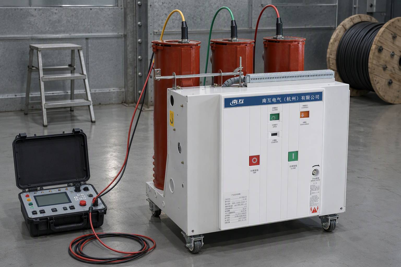
What Does a Vacuum Circuit Breaker Testing Procedure Cover?
Testing happens in three windows, and confusing them is the most common planning error on a switchgear project. Each window has a different purpose and leaves a different document behind.
- Factory routine tests — performed on each individual apparatus before it leaves the works, to reveal faults in material or construction.
- Site acceptance and pre-energisation commissioning — performed after installation and before the circuit enters service, to prove that transport, storage and assembly have damaged nothing and that the installed scheme is correct.
- Periodic in-service testing — performed at intervals set by the operator's maintenance policy, and after abnormal events, to trend condition rather than to prove a new installation.
The standards map onto those windows. IEC 62271-1 covers AC switchgear and controlgear above 1 000 V, indoors or outdoors, up to 60 Hz; the breaker itself is covered by IEC 62271-100, which applies to three-phase AC circuit breakers above 1 000 V at 50 Hz and/or 60 Hz. Those documents define the tests; your project specification defines the numbers you accept, so where a figure below comes from a standard edition it is attributed.
Stage 1 — Factory Routine Tests: What Must the Manufacturer Prove?
Routine tests reveal faults in material or construction, and are not the same thing as type tests. IEC 62271-1:2007 states that they should be made wherever reasonably practicable at the manufacturer's works on each apparatus, so that the unit shipped matches the design on which the type tests were passed, and that by agreement any routine test may be made on site. The same edition lists them as dielectric tests on the main circuit, tests on the auxiliary and control circuits, measurement of main circuit resistance, a tightness test, and design and visual checks.
Dielectric test on the main circuit
A dry, short-duration power-frequency voltage test is applied to the main circuit, following the high-voltage test techniques of IEC 60060-1, with each pole or transport unit tested in new, clean and dry condition. The test proves nothing useful if the insulation is contaminated or damp, so this is as much preparation as measurement. IEC 62271-1:2007 allows it to be omitted where insulation consists only of solid-core insulators and air at ambient pressure, provided the clearances — between phases, across open switching devices and to the frame — are verified dimensionally against the dimensional (outline) drawings. The record should state which route was taken.
Measurement of main circuit resistance
For the routine test, the resistance of each pole is measured under conditions as similar as possible — ambient air temperature and points of measurement — to the corresponding type test, with a test current inside the range given by the standard. IEC 62271-1:2007 states that the measured resistance shall not exceed 1.2 times the resistance measured before the temperature-rise test. Confirm the clause and the figure in the edition your specification calls up.
Tests on auxiliary and control circuits
The auxiliary and control circuits are inspected against the circuit diagrams and their insulation is proved by a power-frequency test; IEC 62271-1:2007 states a test voltage of 1 kV for 1 second. In practice the routine test also covers terminal numbering, coil ratings, anti-pumping and correct operation of the closing, opening and auxiliary contacts — the area where most commissioning problems surface.
Vacuum interrupter integrity and tightness
On a vacuum breaker this is the requirement that matters most. IEC 62271-1:2007 requires each vacuum tube to be identified by its serial number and its vacuum pressure level to be tested and documented by the interrupter manufacturer. After assembly, that level is proved by a significant routine dielectric test across the open contacts, at a voltage stated by the manufacturer, carried out after the mechanical routine test. What the requirement asks for is traceability by serial number plus a dielectric proof on the assembled device. For gas-filled equipment, routine tightness follows the standard's procedures for controlled, closed or sealed pressure systems.
Design and visual checks, and where the type tests fit
The routine programme closes with checks against the purchase specification: nameplate ratings and serial numbers, interlocks, position indication, degrees of protection, earthing and the accessories actually ordered. Type tests are separate, design-level evidence: in the 2007 edition of IEC 62271-1 they comprise dielectric tests, radio interference voltage, circuit resistance measurement, temperature rise, short-time and peak withstand current, verification of protection, tightness, electromagnetic compatibility and additional tests on auxiliary and control circuits. A buyer should expect that evidence to accompany the equipment, not have a site crew reproduce it.
Stage 2 — Site Acceptance and Pre-Energisation Commissioning
Site testing answers a different question: did the equipment survive transport, storage and installation, and is the installed assembly safe to energise? A vacuum breaker is rarely commissioned alone — it sits inside a metal-enclosed assembly alongside current transformers, voltage transformers, cable terminations, earthing and the protection scheme, and the assembly standard above 1 kV up to and including 52 kV is IEC 62271-200:2021. Test the breaker as part of the scheme.
Which tests should be done before a VCB is energised?
A pre-energisation programme for a 10–35 kV vacuum breaker normally covers insulation resistance on the primary circuit (pole to earth, pole to pole and across the open contacts) and on the secondary wiring; a power-frequency withstand test on the main circuit where the specification requires it; contact resistance on each pole; a vacuum integrity check on each interrupter; mechanical operation with timing; functional checks of the trip, close, anti-pumping, interlock and indication circuits, including a trip from each protective relay output; and any monitoring devices fitted. The list is a shape, not a specification: applied voltages, durations and acceptance values come from the project specification and the standard edition it invokes, and belong in the test plan agreed before the outage.
How is contact resistance measured?
With the breaker isolated and closed, a low-resistance ohmmeter or micro-ohmmeter injects a direct current through one pole at a time and reads the voltage drop across the main contacts, so the result includes the contacts, the interrupter's internal connections and the local terminations. Record each pole separately with the ambient temperature and the instrument used, then compare the three phases with one another as well as against the reference: a pole reading materially higher than its neighbours points to a poor contact, a loose or corroded connection or, on older equipment, a degraded interrupter. Resistance recorded without the temperature at which it was taken makes that comparison indefensible later.
Insulation resistance and power-frequency withstand
Insulation resistance, measured with a suitable tester once the assembly is clean, dry and isolated, is a fast and repeatable indicator of moisture, contamination or a damaged cable termination. Take it on the secondary wiring as well as the primary — a damp terminal box is a classic cause of nuisance tripping. The power-frequency withstand test on the main circuit is the more demanding check and needs a mobile test set, controlled clearances, reliable earthing and a safe system of work. Because the applied voltage and duration are set by the standard and the project specification, agree them in the test plan beforehand rather than deciding at the panel.
How do you confirm the interrupters still hold vacuum?
It looks for one failure mode: loss of vacuum in an interrupter, which removes the dielectric strength across the open contacts and, with it, the ability to interrupt fault current. The field method applies a specified voltage across the open contacts of each interrupter and compares the result with the value stated by the interrupter manufacturer. IEC 62271-1 builds the same principle into routine practice for assembled vacuum switchgear: use the test voltage the manufacturer states, and make the dielectric proof after the mechanical operation tests.
Mechanical operation and timing
Operate the breaker several times with its own closing and opening circuits, not by hand. Record whether each operation completed, whether the mechanism latched, whether position indication and auxiliary contacts changed state correctly, and how the mechanism behaved at the limits of its auxiliary supply voltage. Timing normally covers closing time, opening time, pole discrepancy and, where the trip circuit is under test, overall trip time from energisation of the trip coil. Compare these figures with earlier values from the same unit, not only the factory sheet: a mechanism that is drifting usually fails long before a vacuum interrupter does.
Auxiliary, trip and control circuits
Most site problems appear here. The trip and close circuits are proved by operation, including a trip from every protective relay output and from any manual trip device; anti-pumping is tested by holding the close command; interlocks are proved by attempting the operations they are meant to prevent, with the breaker isolated. Simulate loss and restoration of the auxiliary supply rather than assuming how the mechanism behaves, identify every secondary core at both ends, and prove the trip circuit monitoring — an unmonitored trip circuit fails silently.
Test Matrix: What Each Test Detects and What the Record Shows
The table below is the working summary. Acceptance values are deliberately absent, because they belong to the standard edition and the project specification.
| What it detects | When performed | What the record shows | |
|---|---|---|---|
| Main circuit resistance | Contact and connection degradation, loose or corroded terminations, internal wear in the interrupter | Factory routine test; site acceptance; each in-service visit | Resistance per pole, ambient temperature, instrument and calibration status, reference value compared against |
| Insulation resistance | Moisture, contamination and insulation damage in the primary circuit and the secondary wiring | Site acceptance; in-service testing | Value for each measurement point with the test voltage and duration applied |
| Power-frequency withstand on the main circuit | Dielectric weakness across open contacts, between poles and to earth | Factory routine test; site acceptance where specified | Applied voltage, duration, method used (test or dimensional verification) and result |
| Vacuum interrupter integrity | Loss of vacuum in an interrupter, and therefore loss of the ability to interrupt fault current | Factory routine test on the assembled device; site acceptance; after any suspected event | Interrupter serial number, applied voltage, per-pole result |
| Mechanical operation and timing | Mechanism faults, failure to latch, maloperation, interlock and auxiliary contact defects | Factory routine test; site acceptance; in-service testing | Number and type of operations, close and open times, pole discrepancy, observations |
| Auxiliary, trip and control circuits | Wiring errors, incorrect relay and coil operation, defective anti-pumping or interlocks, unmonitored trip paths | Factory routine test; site acceptance; in-service testing | Circuits proved, relays tripped from, anti-pumping and interlock results, insulation test value |
| Tightness of the insulating medium, where applicable | Loss of insulating or operating medium from the equipment | Factory routine test; in-service testing | Method used, serial numbers of the tubes or gas compartments, documented result |
Stage 3 — In-Service Testing and How Often to Retest
Once the circuit carries load, the objective changes from proving an installation to tracking condition, and the vacuum circuit breaker testing procedure becomes a comparison exercise: the same measurements, taken the same way with the same class of instrument, so that a trend becomes visible before a failure does.
The interval itself is a policy decision, and no universal figure can be quoted honestly. Retest frequency depends on the operator's maintenance standard, the duty the breaker sees, the number of operations it has performed and how critical the circuit is; operators set their own intervals from operating experience and manufacturer recommendations. Baseline resistance, insulation and timing values are taken at commissioning and filed with the unit, and each visit repeats them, with any change investigated rather than merely recorded. Alongside the calendar, condition-based testing is triggered by events: a fault interruption near rated breaking current, an abnormal operation, water ingress, or a long period left unoperated. Three checks carry the most diagnostic weight — the contact resistance trend per pole, the vacuum integrity check, and the mechanical timing figures. Where a circuit relies on monitoring rather than scheduled testing, the operation of the devices covered in the guide to faulted circuit indicators should be verified during the same visit.
What Should a Test Record Contain?
A testing procedure is only as valuable as the record it leaves behind, because the next engineer will judge the unit from that document alone. A usable record identifies the equipment — station, bay, breaker type and serial number, and each interrupter serial number — and states the date and the ambient and equipment temperature.
For every test it should give the instrument or test set used with its calibration status; the quantity applied; the value measured for each pole, phase or circuit rather than only the worst one; the acceptance limit or reference value being compared against; and an unambiguous pass or fail statement. Where a value is out of limit, the record should say what was done about it. It should be signed by the person who performed the test and witnessed where the specification requires it. IEC 62271-1:2007 notes that routine test reports are normally not necessary unless otherwise agreed between manufacturer and user — which is why a project should agree, in the purchase order, that routine test results for the supplied units will be handed over.
What to Ask a Supplier to Supply
Because acceptance values and the evidence trail are contract items, the most useful questions to a supplier are documentary. Ask which standard edition the equipment is designed and tested to, and for a type-test report from an accredited laboratory matching the rating and design quoted, not a similar model. Ask for routine test results for the specific units being delivered, with vacuum interrupter serial numbers, and who performed the tests, on what instrument, reported per pole rather than in aggregate. Ask for the test voltage the interrupter manufacturer states for the vacuum integrity check, because your commissioning contractor will be applying it. And ask what reference data ships with the order: circuit diagrams, mechanical and timing reference values, insulation resistance data, and the interrupter documentation needed to judge measurements taken years later.
Nahu Group manufactures vacuum circuit breakers and medium-voltage switchgear for 10–35 kV distribution and industrial networks, alongside current transformers, voltage transformers and metering equipment for the same substations. The breaker range sits within our catalogue of high-voltage electrical equipment, and for commercial context, vacuum circuit breaker sales in the United States explains how the market side of these units is usually structured. Whatever the manufacturer, the question worth putting on the record is the same one: what documentation ships with the unit, and does it describe the unit you are receiving?
Frequently Asked Questions About VCB Testing
What does a vacuum circuit breaker testing procedure cover?
It covers the electrical, mechanical and functional checks a VCB is given across its life: routine tests in the factory, site acceptance and pre-energisation checks in the substation, and periodic in-service testing once the circuit is live. The core measurements are main circuit resistance, insulation resistance and power-frequency withstand, vacuum interrupter integrity, mechanical operation and timing, and the auxiliary and trip circuits.
What tests does a VCB need before energisation?
A pre-energisation programme normally includes insulation resistance on the primary circuit and the secondary wiring, a power-frequency withstand test on the main circuit where the specification requires it, contact resistance per pole, a vacuum integrity check on each interrupter, mechanical operation with timing, and functional checks of the trip, close, anti-pumping, interlock and indication circuits. The scope, the applied voltages and every acceptance value come from the project specification and the applicable standard edition.
How is contact resistance measured on a vacuum circuit breaker?
With the breaker isolated and closed, a low-resistance ohmmeter or micro-ohmmeter injects a direct current through one pole at a time and measures the voltage drop across the main contacts. Each pole is recorded separately, with the ambient temperature and the instrument used, and the values are compared pole to pole and against the reference. IEC 62271-1:2007 states that the routine measured resistance shall not exceed 1.2 times the resistance measured before the temperature-rise test; confirm the current edition and the project specification.
What does a vacuum integrity check look for?
It looks for loss of vacuum in an interrupter, which removes the dielectric strength across the open contacts and the ability to interrupt fault current. The field method applies a specified voltage across the open contacts of each interrupter and compares the result with the value stated by the interrupter manufacturer. IEC 62271-1:2007 requires each vacuum tube to be identified by serial number, its vacuum pressure level to be tested and documented by the interrupter manufacturer, and the assembled device to be proved by a dielectric test across the open contacts after the mechanical routine test.
How often should you retest a vacuum circuit breaker?
There is no single interval that applies to every installation. In-service retest frequency depends on the operator's maintenance policy, the duty the breaker sees, the number of operations and the criticality of the circuit, and it is normally set from operating experience plus manufacturer recommendations. On top of the schedule, condition-based testing is triggered by events such as a fault interruption near rated breaking current, an abnormal operation or water ingress.
Can routine tests be carried out on site instead of in the factory?
Yes, by agreement between manufacturer and user. IEC 62271-1:2007 states that routine tests should be made at the manufacturer's works wherever reasonably practicable, and that by agreement any routine test may be made on site. The same test record content should be produced either way.
What should a vacuum circuit breaker test record contain?
Identification of the station, bay and unit with each interrupter serial number; the date and ambient conditions; the instrument or test set with its calibration status; the test applied and the value measured for every pole, phase or circuit; the acceptance limit or reference value the result is compared with; a pass or fail statement; and the signature of the person who performed the test, with a witness signature where the specification requires one. Out-of-limit results should state what corrective action was taken.
Is a supplier's type-test certificate enough evidence for a project?
They are different documents. A type-test report from an accredited laboratory describes a design tested at a point in time, while routine test results relate to the individual unit being shipped. For a project, request both: the type-test report matching the design and rating, routine test results for the units you are receiving including interrupter serial numbers, and confirmation of the standard edition the evidence was produced against.
Sources and Further Reading
- IEC 62271-1:2017 — common specifications for AC switchgear and controlgear above 1 000 V; the part of the 62271 series that defines the routine and type test framework.
- IEC 62271-100:2021 — AC circuit-breakers; the product standard for the breaker itself, covering direct making and breaking tests above 1 000 V.
- IS/IEC 62271-1 : 2007 (Bureau of Indian Standards adoption of IEC 62271-1:2007) — the source of the routine test list, the 1 kV / 1 s auxiliary circuit test, the 1.2 × resistance limit and the vacuum switchgear requirement quoted above. Verify against the edition your project calls up.
- IEC 62271-200:2021 — metal-enclosed switchgear and controlgear above 1 kV up to and including 52 kV; the assembly standard behind site acceptance of a 10–35 kV switchboard.
Testing a vacuum circuit breaker is not one test but a chain: routine tests that prove a unit against its design, commissioning tests that prove an installation, and in-service measurements that prove a trend. Every link depends on the same discipline — a stated method, a calibrated instrument, a recorded value, and a limit taken from the applicable standard edition and the project specification.
For 10–35 kV vacuum circuit breakers and switchgear, Nahu Group supplies the equipment and can provide the documentation package a project requires. See the product range, or talk to the engineering team about the test evidence and reference data your project requires.
Published September 21, 2026 · Nahu Group (NAHU Electric Technology)