
High-voltage electrical equipment is the group of devices used to generate, transform, measure, protect, switch, and distribute electricity at voltage levels that require specialized insulation, clearances, and operating procedures. In practical projects, this includes switchgear, circuit breakers, current transformers, voltage transformers, surge arresters, cables, busbars, and power transformers used in energy transmission and industrial power distribution.
For NAHU Group’s audience in Vietnam, the topic is especially relevant when selecting current transformers and related measurement equipment for substations, factories, solar plants, commercial buildings, and utility networks. A correct definition is not only about voltage rating; it is also about safety, measurement accuracy, system protection, and long-term reliability under local operating conditions.
What is high-voltage electrical equipment?
High-voltage electrical equipment is equipment designed to operate safely and reliably at voltages high enough to create serious risks of electric shock, arc flash, insulation breakdown, and equipment failure if it is incorrectly specified or handled. In many engineering contexts, “high voltage” is used broadly for medium-voltage and high-voltage power systems, especially when discussing switchgear, substations, transformers, and instrument transformers.
The defining feature is controlled electrical stress. A low-voltage device may use compact insulation and short clearances, but high-voltage apparatus must manage electric fields, heat, fault currents, pollution, humidity, and mechanical forces. That is why insulation materials, enclosure design, creepage distance, earthing, and testing standards matter as much as the nameplate voltage.
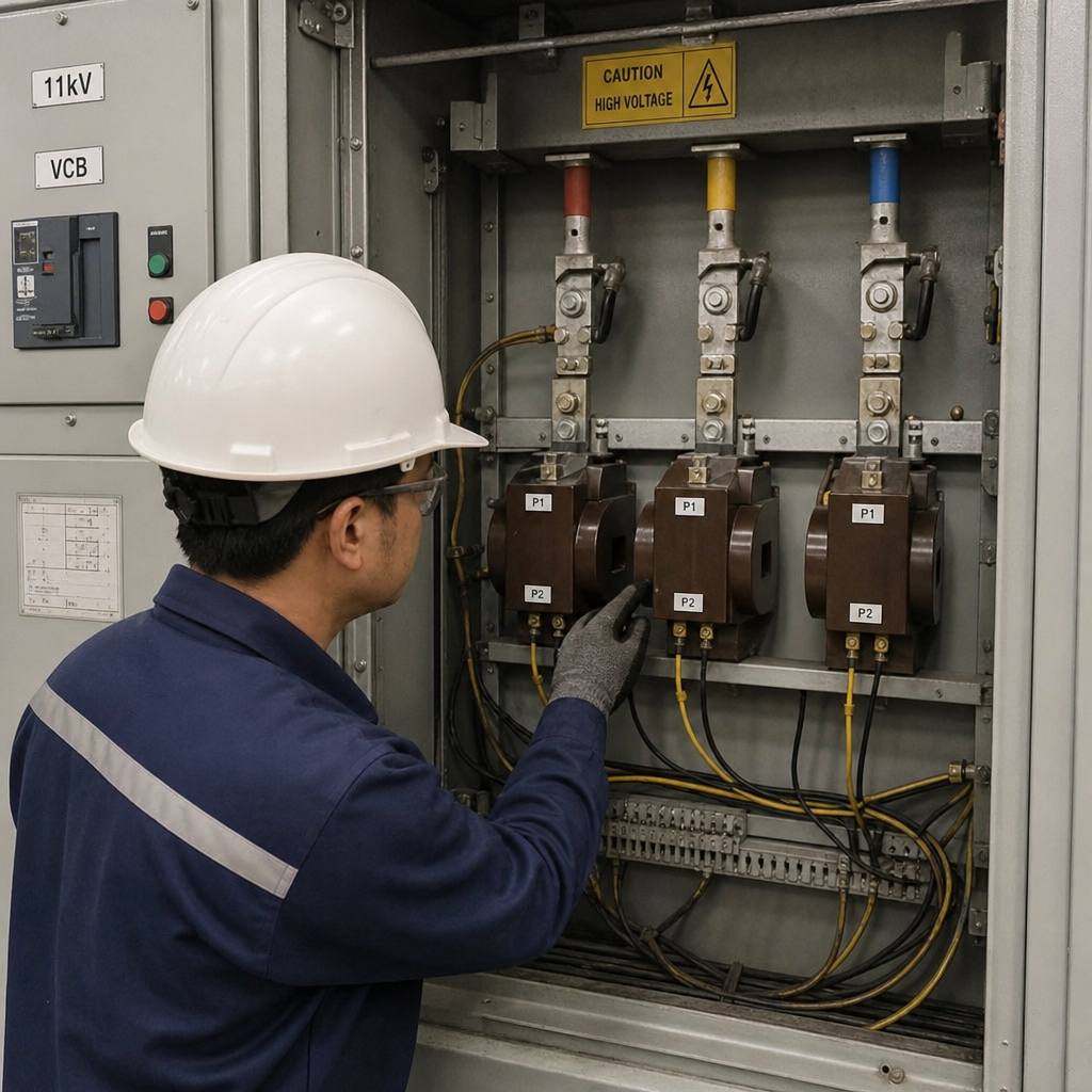
In a measurement system, current transformers are a key part of this equipment family. They reduce large primary currents into standard secondary signals, commonly for meters, protection relays, and power quality monitoring. Without CTs, engineers could not safely measure feeder currents, detect faults, or verify load behavior in high-current circuits.
Core components and defining characteristics
High-voltage equipment is usually selected as a system, not as isolated products. A switchgear panel, for example, may combine busbars, circuit breakers, protection relays, current transformers, voltage transformers, earthing switches, indicators, and interlocks. Each part must match the project’s voltage level, fault current, installation environment, and operating purpose.
Key characteristics include:
- Rated voltage: The maximum system voltage the device is designed to withstand during normal service.
- Insulation level: The ability to resist power-frequency voltage, lightning impulse, switching impulse, and temporary overvoltage.
- Rated current: The continuous current the equipment can carry without exceeding temperature limits.
- Short-time withstand current: The fault current the equipment can tolerate for a specified duration until protection clears the fault.
- Measurement or protection accuracy: Especially important for current transformers and voltage transformers.
- Environmental suitability: Indoor or outdoor installation, humidity, coastal air, industrial dust, and temperature.
- Mechanical and safety design: Enclosures, barriers, interlocks, earthing points, and safe access for maintenance.
For Vietnamese buyers, these details affect tender compliance, installation cost, commissioning risk, and lifecycle performance. Procurement teams should avoid choosing only by voltage and price because two products with the same voltage rating can perform very differently in measurement accuracy, insulation endurance, and protection coordination.
How does high-voltage equipment work in a power system?
High-voltage equipment works by moving electrical energy efficiently while keeping dangerous voltage and current under control. Transformers step voltage up for energy transmission over long distances, then step it down for power distribution to industrial zones, commercial facilities, and end users. Switchgear controls and isolates circuits, while protection devices detect faults and remove unsafe sections from service.
Current transformers support this process by creating a safe, proportional secondary current for instruments and relays. For example, a feeder carrying 800 A may use a CT ratio such as 800/5 A or 800/1 A, depending on the metering or protection system. The basic relationship is:
Secondary current = Primary current ÷ CT ratio
If a 1000/5 A CT measures 600 A on the primary conductor, the ideal secondary current is 3 A. In real systems, accuracy class, burden, saturation, and wiring length influence the final signal. That is why engineers must review not only the current ratio but also VA burden, accuracy class, knee-point requirements for protection CTs, and the relay or meter input.
For measurement equipment, the practical goal is simple: deliver a reliable signal without exposing operators or instruments to primary voltage and current. For protection systems, the goal is faster and more dependable fault detection. A poorly selected CT can under-report current, saturate during faults, or cause nuisance trips, all of which create operational and commercial risk.
Current transformers in high-voltage measurement
Among high-voltage electrical equipment, current transformers deserve special attention because they connect the power circuit to the control and measurement system. They may look like passive components, but they influence metering accuracy, relay performance, energy management, and fault analysis.
Common CT types used in industrial and utility projects include:
- Wound primary CTs: Suitable for lower primary currents and applications requiring defined primary turns.
- Window or ring CTs: Installed around a busbar or cable, often used in switchboards and metering panels.
- Bar-type CTs: Designed with a primary conductor through the core, common in medium-voltage switchgear.
- Split-core CTs: Useful for retrofit installations where disconnecting cables is difficult.
- Protection CTs: Built to remain useful at higher fault currents before saturation.
- Metering CTs: Designed for accuracy in the normal operating range used for billing, monitoring, or energy audits.
When sourcing CTs, engineers and procurement professionals should confirm the system voltage, primary current, secondary output, accuracy class, burden, insulation level, frequency, mounting style, and applicable standards. Contractors should also check the available installation space because CT window size and terminal orientation can affect panel assembly.
If you are sourcing current transformers for medium-voltage switchgear, industrial metering, or utility projects, explore NAHU Group’s current transformer range or contact the team for application support. The best selection usually starts with a single-line diagram, load current data, relay or meter model, and installation drawings.
Why electrical safety depends on insulation and coordination
Electrical safety in high-voltage systems depends on preventing unintended contact, controlling arcing risk, and ensuring faults are cleared before equipment is damaged. Insulation materials such as epoxy resin, porcelain, silicone rubber, transformer oil, SF6 alternatives, and air insulation are selected according to voltage stress, environment, mechanical strength, and maintenance requirements.
For current transformers, insulation is not just a housing detail. It separates the primary circuit from the secondary circuit and from grounded metal parts. If insulation fails, the result can be dangerous voltage transfer, equipment damage, relay failure, or an outage. This is why routine inspection, correct earthing of CT secondary circuits, and safe handling procedures are essential.
Important safety practices include:
- Never open-circuit a CT secondary while primary current is flowing. Dangerous secondary voltage can develop.
- Confirm polarity before commissioning. Incorrect polarity can cause wrong metering or protection behavior.
- Match CT burden to the connected devices and cable length. Excess burden can reduce accuracy.
- Use proper shorting terminals during testing. This protects personnel and instruments.
- Keep insulation surfaces clean and dry. Pollution and moisture can reduce creepage performance.
- Document ratio, class, and wiring. Good records help maintenance teams troubleshoot faster.
These points are familiar to experienced electrical engineers, but they are also procurement issues. A cheaper component that complicates installation or fails testing can delay energization and increase project cost.
Practical examples in Vietnam-focused projects
High-voltage and medium-voltage systems appear in many local applications, from utility substations to manufacturing plants. In each case, measurement equipment must support both technical operation and commercial accountability.
Typical examples include:
- Industrial feeders: CTs measure load current for energy monitoring, demand control, and overload protection.
- Solar and renewable plants: Instrument transformers support grid connection metering, protection, and supervisory control.
- Commercial buildings: CTs feed multifunction meters for tenant billing, power quality checks, and energy reporting.
- Utility substations: Protection CTs and voltage transformers provide relay inputs for feeder, transformer, and busbar protection.
- EPC projects: Standardized CT specifications help contractors reduce panel design changes and simplify commissioning.
- Distribution partners: Clear model selection improves quotation speed and reduces mismatch between tender documents and delivered goods.
A useful selection approach is to separate the application into measurement and protection needs. Metering CTs prioritize accuracy around normal load. Protection CTs prioritize reliable performance during abnormal current and fault conditions. Some projects need both functions, often with separate CT cores, so the relay and meter each receive the signal they require.
High-voltage equipment is a system decision
Choosing high-voltage electrical equipment is not only a purchasing task; it is a system engineering decision. Voltage regulation, insulation coordination, short-circuit capability, metering accuracy, and maintainability must work together. This is especially true for electrical transformers, switchgear, and instrument transformers that operate as one protection and measurement chain.
For buyers, the safest path is to specify the operating conditions clearly and ask suppliers to confirm compatibility rather than offering a model number alone. For engineers, the priority is to align CT ratios, relay settings, transformer ratings, and protection philosophy before installation begins. For contractors and EPC companies, early coordination reduces rework at the panel, cable, and commissioning stages.
High-voltage systems reward careful specification. When CTs, insulation materials, protective devices, and measurement instruments are selected as a coordinated package, the result is safer operation, better data, and more dependable power distribution over the life of the project.
Published August 20, 2026 · Nahu Group (NAHU Electric Technology)