
On a single-line diagram, the vacuum circuit breaker symbol is the square — or the contact with a small interrupting chamber drawn across it — that marks the one device on the feeder allowed to open fault current. Everything else drawn in series with it, the disconnector, the earthing switch, the load break switch, exists to make that interruption safe rather than to replace it. Read that symbol correctly and the rest of the drawing falls into place.

Tender packages arrive with a single-line diagram, a device schedule and a general arrangement, and the three are supposed to agree. When they do not, the disagreement usually sits in the switching device symbols, because that is where a drafter copies a block from an old project without re-reading what it means. This is a short guide to reading those blocks the way an evaluating engineer has to: what the symbol promises, what it deliberately leaves out, and the three places where it is confused with a device that cannot do the job.
What Does a Vacuum Circuit Breaker Symbol Tell a Buyer?
The symbol states a function, not a technology. A square on the line, or a contact with an arc-control element drawn across it, says: this device interrupts load current and it interrupts fault current. The letters VCB beside it, or the device number in the schedule, say the interrupting medium is vacuum. Keeping those two statements apart is what lets you audit a package, because a drawing can show the correct interrupting function next to a schedule line naming a device that cannot perform it — and the reverse.
What the symbol never tells you is what the purchase actually depends on: rated short-circuit breaking current, operating sequence, mechanical endurance, spring or permanent-magnet mechanism, draw-out or fixed. Those belong in the schedule and in the type test report. The type-test basis for them is IEC 62271-100, the circuit-breaker part of the switchgear family, while the shared ratings and service conditions the whole assembly has to meet come from IEC 62271-1.
Does the Symbol Change Indoors or Outdoors?
No. The symbol describes what the device does in the circuit, so the same block appears whether the breaker is a fixed indoor unit bolted into a metal-enclosed panel or a pole-mounted outdoor unit with its own bushings and frame. What changes around the symbol is the enclosure, the cable or overhead line it terminates, and the auxiliary symbols for current transformers that are built into the outdoor types.

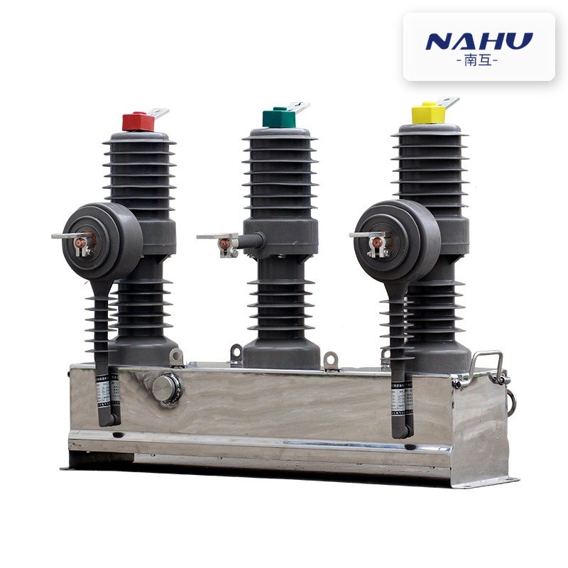
The outdoor ZW10-12 type shows why a drawing cannot be priced from its symbol count. Three porcelain bushings, an integral disconnecting blade set and a manual operating mechanism all sit on one frame, yet on the single line they reduce to one breaker symbol plus an isolating gap. Two quotations can carry identical symbols and different hardware, so the comparison has to be made on the vacuum circuit breaker range and its model list, line by line against the schedule.
What Sits Around the Breaker on the Same Feeder
A feeder rarely ends at the breaker. Between the busbar and the cable you will normally find a current transformer for protection and metering, sometimes a voltage transformer or a three-phase set, an earthing switch, and the cable termination. Each has its own symbol and each has a position that carries meaning: a CT drawn on the busbar side of the breaker measures fault current the breaker will clear, while the same CT on the cable side measures what leaves the panel.
The instrument transformers are also where the drawing stops being a schematic and becomes a configuration document. A ring-type CT mounted over the bushing, a three-phase VT set in a separate compartment, a zero-sequence core-balance CT around the three cores — these are three different symbols and three different secondary wiring schemes, and the protection engineer needs the symbol to match the scheme that was actually quoted.
Vacuum Circuit Breaker Symbol vs Load Break Switch Symbol
These two are the pair most often drawn alike, and the difference is not cosmetic. A load break switch makes and breaks load current, and it may be given a defined short-time and making capability, but it does not interrupt fault current. On the drawing the distinction has to be visible without reading the schedule, because the two devices look similar in a single-line sense and completely different in a short-circuit study.
| Question the symbol has to answer | Circuit breaker | Load break switch |
|---|---|---|
| Can it clear a fault on its own? | Yes — rated short-circuit breaking current is a nameplate value | No — load current and defined overload only |
| How is the interrupting function drawn? | Contact with an interrupting chamber, or a square block on the line | Plain contact, sometimes with an arc-control annotation |
| What protection has to accompany it? | Its own relay and trip circuit, or a self-powered protection unit | A fuse or an upstream breaker that clears the fault |
| Typical position in the network | Feeder, incomer, transformer protection | Ring ways, sectionalising points, transformer tee-off with fuses |
| Where the buyer checks the difference | Type test report for breaking capacity and operating sequence | Making and short-time withstand values, plus fuse coordination |
If a ring main unit drawing shows a breaker symbol on a ring way, either the design is unusual or the drawing is wrong. Ring ways are normally load break switches, and the load break switch product page sets out the ratings that have to appear on the schedule alongside the symbol. The comparison of load break switches with breakers and isolators covers the same boundary from the device side.
Vacuum Circuit Breaker Symbol vs Disconnector Symbol
The disconnector is drawn as an open blade with a visible gap at one end. That gap is the whole point: it exists to give a visible isolating distance for work, and it is never intended to interrupt current. Its own standard, IEC 62271-102, treats it as a device with making and short-time withstand ratings rather than a breaking rating. When a drawing shows a gap in series with a breaker, that is correct practice: the breaker interrupts, the gap isolates, the earthing switch then makes the circuit safe.
Problems start when the gap is used where a breaker belongs. On a feeder that has to clear a transformer fault, a disconnector will simply hold the arc until something upstream operates, which is exactly the outcome the protection study was written to avoid. The isolating switch range is built for that isolating duty and says so in its ratings, and the isolator selection notes explain which indoor and outdoor forms fit which position.
Three Symbol Conventions That Trip Up Tender Reviews
Draw-out and fixed units are drawn with the same functional block in most conventions, and the difference appears only as a note or a dashed enclosure. That is where the first error lives: a schedule specifies a withdrawable unit, the drawing shows a fixed pattern, and nobody notices until the switchgear room is being laid out. The second is the handcart or truck symbol used for a fixed pattern — it implies a withdrawable device that is not in the quotation.
The third is a breaker drawn without its earthing switch. Earthing is a separate function with a separate symbol, and if it is missing from the single line it is usually missing from the bill of materials. On a metal-enclosed panel the consequence is a late variation order for earthing switches and interlocking, quoted after the panel steel is cut. The full symbol set for switchgear drawings is the reference to check a package against, and the ring main unit diagram walkthrough shows the same convention applied to a compact substation.
What to Write in the RFQ and the Drawing Schedule
State the interrupting duty, not the device name alone. A schedule line that says only "VCB, 12 kV" leaves the supplier free to offer the lowest breaking capacity in the family, and the reviewer with no basis to reject it. These are the entries worth demanding for each breaker position:
- Rated voltage, rated normal current and rated short-circuit breaking current, with the operating sequence the type test covers
- Short-time withstand current and duration, so the busbar and the earthing arrangement can be checked against it
- Mechanism type and the number of stored operations, spring or permanent magnet, with the charging arrangement
- Fixed or withdrawable, and for withdrawable units the compartment class and the interlocks provided
- Auxiliary contacts, tripping and closing coil voltages, and the anti-pumping arrangement
- Type test report and routine test record for the offered design, not a catalogue extract
Where Nahu Group Fits
Nahu Group builds indoor and outdoor vacuum circuit breakers for 12 kV to 40.5 kV distribution networks, in spring and permanent-magnet mechanisms, including pole-mounted intelligent types with built-in current transformers. The models named in this article — ZN63A (VS1)-12 indoors, ZW10-12 outdoors — are catalogue items in the range. To get a configuration, send the single-line diagram with its symbol convention, the device schedule with the ratings above, and the service conditions: ambient temperature, altitude, pollution level, and whether the panel is indoor metal-enclosed or pole-mounted.
Frequently Asked Questions
Is a vacuum circuit breaker symbol different from an SF6 breaker symbol?
No. The single-line symbol shows the interrupting function, and both media perform the same function, so the same block is used. The medium appears in the device designation and the schedule, not in the symbol. What does differ is the surrounding equipment — gas density monitoring for SF6, and none for vacuum.
Why is a breaker sometimes drawn as a square and sometimes as a contact?
Both conventions exist and both are accepted, but a package should use one consistently. The square reads as a complete switching device with an interrupting chamber; the contact with an arc-control mark reads as a switching element. Mixing the two inside one drawing set is what makes a reviewer stop and ask which device is actually being quoted.
Can a load break switch be drawn with a breaker symbol if a fuse protects the circuit?
No, and this is the error that survives longest because the combination works electrically. A switch-fuse combination clears faults through the fuse, but the switch itself still cannot interrupt fault current, so it keeps its own symbol with the fuse drawn beside it. Drawing it as a breaker misstates the short-circuit duty of the panel.
Where should the current transformer symbol sit relative to the breaker?
It depends on the protection scheme, not on drawing habit. A CT on the busbar side sees fault current from the feeder and is used for feeder protection; a CT on the cable side sees the current leaving the panel and suits metering or downstream protection. Decide the scheme first, then draw the CT where the scheme needs it.
Does the symbol tell me whether the breaker is suitable for capacitor switching?
No. Capacitor and reactor switching duties impose restrike and inrush requirements that a general-purpose breaking rating does not cover. They are stated separately in the specification and demonstrated by specific type tests. Ask for them explicitly if the feeder has a capacitor bank or a filter branch.
Sources and Further Reading
- IEC 62271-100:2021 — High-voltage switchgear and controlgear, Part 100: Alternating-current circuit-breakers — the type-test standard behind rated short-circuit breaking current, operating sequence and mechanical endurance
- IEC 62271-102:2018 — High-voltage switchgear and controlgear, Part 102: Alternating current disconnectors and earthing switches — why the disconnector carries making and short-time ratings rather than a breaking rating
- IEC 62271-1:2017 — High-voltage switchgear and controlgear, Part 1: Common specifications — service conditions, ratings and the dielectric and mechanical requirements shared by the whole assembly
Published Nov 9, 2026 · Nahu Group (NAHU Electric Technology)