
Electrical switchgear symbols are the vocabulary of the single-line diagram, and the diagram is the only document that every discipline on a substation project reads. A protection engineer, a panel builder, a cable jointer and a commissioning technician all work from the same drawing, and they all interpret a square, a blade or a pair of overlapping circles the same way — provided the drawing uses one convention consistently and says which one it uses.
The problems start when conventions are mixed. A breaker drawn as a square in one place and as a blade with an arc chute in another reads as two different devices. A disconnector drawn without its open gap looks like a breaker that has been left out. A CT shown as a single circle on the line can be mistaken for a cable joint by anyone who learned the symbol on a different standard.
This guide covers the symbols that appear on a medium-voltage distribution diagram, from the busbar to the cable tail: what each one means, how IEC and IEEE/ANSI practice differ, and how to read a feeder from one end to the other without guessing. It is a reading aid, not a substitute for the standard edition named in the project's drawing title block.
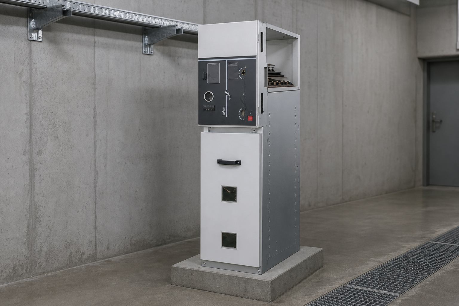
Why Do Switchgear Symbols Matter More Than They Look?
A single-line diagram is compressed. One line stands for three phases, one square stands for a device that may contain a vacuum interrupter, a mechanism, a trip coil and three sets of auxiliary contacts, and one circle stands for an instrument transformer with a ratio, a burden and an accuracy class written beside it. The compression is what makes the diagram useful, and it is also what makes a wrong symbol expensive: it survives into the panel layout, the interlock schedule and the cable schedule before anyone notices.
Symbols also carry the safety argument. Whether a circuit can be earthed at a particular point, whether the isolation is visible, whether the earthing switch can be closed with the breaker closed — all of that is stated on the diagram by symbol placement rather than in a note. A diagram that draws an earthing switch on the line side of a disconnector has said something specific about where the earth is applied and what it protects.
So the rule for a project is simple: one convention, stated once, used everywhere. Mixing IEC and ANSI symbols on the same drawing is not a stylistic choice; it is an ambiguity that someone will resolve incorrectly at 2 a.m. during a restoration.
Which Symbols Come First: Busbar, Cable and Transformer
The passive parts of the diagram are the ones that define the topology, and they are the least standardized across conventions. Read them first, because everything else is placed relative to them.
| Symbol as drawn | Meaning | Notes on convention |
|---|---|---|
| A heavy horizontal line | Main busbar | Thickness implies current path, not rating; the rating belongs in the schedule |
| A single line leaving the busbar downward | Feeder or branch circuit | One line represents all three phases unless a phase is called out |
| Two overlapping circles | Two-winding power transformer | Three circles for a three-winding unit; a zig-zag or delta marking is added where the vector group matters |
| A circle with a winding symbol inside, or two circles with a ratio beside them | Voltage transformer | Frequently drawn as two circles for the primary and secondary windings |
| A circle threaded onto the line, with a ratio such as 400/5 | Current transformer | The circle sits on the conductor; a bar-primary CT may be drawn as a single turn through the circle |
| A line ending in a small circle or a flag | Cable termination | The cable number and size are written beside it, not encoded in the symbol |
Two of those entries cause most of the confusion. The first is the VT: a transformer symbol with two circles and a breaker symbol with a square are easy to tell apart, but a VT drawn as a single circle next to a CT drawn as a single circle is not. The second is the CT: when the ratio is written inside the circle rather than beside it, a busy diagram makes the circles look like joints.
Switching Device Symbols: Breaker, Disconnector, Switch and Fuse
Four devices do the switching, and the difference between them is exactly what the symbol has to convey: whether the device can interrupt current, whether the break is visible, and whether it can be closed onto a fault.
| Device | IEC-style representation | IEEE/ANSI-style representation | Interrupts |
|---|---|---|---|
| Circuit breaker | A small square on the line, sometimes with the contact symbol inside | A square, or a contact with an arc-control box, often labelled 52 | Load and fault current |
| Disconnector (isolator) | A blade drawn at an angle with a visible gap | A blade with an open gap, often labelled 89 | No current; provides a visible break |
| Load break switch | A contact with an arc-control device, or a switch symbol marked with its breaking capability | Switch symbol with an arc chute, labelled 89 or 52 depending on duty | Load current only |
| Fuse | A rectangle on the line, or a rectangle with a diagonal | A rectangle, sometimes with the fuse characteristic written beside it | Fault current, once |
| Earthing switch | A blade from the conductor to an earth symbol | Same, often labelled 89G | No load; carries fault current briefly |
The device numbers in the ANSI column come from the standard device-function list, and they are what makes an American drawing readable at a glance: 52 is a breaker, 89 is a disconnector, 50/51 are instantaneous and time-overcurrent protection, 87 is differential. An IEC drawing may carry no numbers at all and rely entirely on the symbol and its label, which is why an IEC drawing travels less well between organisations.
One symbol deserves a warning. A switch drawn without any arc-control mark is a switch, not a breaker, and a diagram that shows it clearing a fault is wrong regardless of the standard used. The distinction between "can break load" and "can break fault" is the single most important thing the switching symbols encode, and it is the one most often blurred by a draftsman who reuses a block.
Measurement Symbols: CT, VT, Meter and Relay
Instrument transformers appear twice on a diagram: once on the primary single-line, as a circle on or beside the conductor, and once on the secondary schematics, as a winding with polarity marks. The link between the two is the reference designation, and a diagram that does not carry it forces the reader to trace by position.
- Current transformer. A circle on the line with the ratio beside it, and the accuracy class and burden in the schedule. Multi-core CTs are drawn as one circle with several secondary cores listed, or as several circles in a row where the diagram is expanded.
- Voltage transformer. Two circles or a circle with a winding, connected between phases or between phase and earth. The connection is part of the symbol: a VT drawn phase-to-earth behaves differently from one drawn phase-to-phase, and the residual winding needs its own representation if earth-fault protection depends on it.
- Meter. A circle with the letter kWh, kvarh or A inside, or a rectangle in a schedule-based drawing. On a single-line diagram the meter is often omitted and shown only in the metering schematic, which is why metering disputes are so often settled by the secondary drawing.
- Protection relay. A rectangle with the ANSI function numbers inside (50, 51, 50N, 87), connected by dashed lines to the CT and VT circuits and to the breaker trip coil. The dashed line is the convention for a control or measurement circuit as opposed to a power circuit.
Polarity marks are the detail that matters most here and is drawn least consistently. A CT secondary drawn without polarity dots cannot be checked against the commissioning test, and a VT residual circuit drawn without its polarity cannot be checked for correct earth-fault operation. Where the diagram is the only document on site, that omission is the difference between a test that proves something and a test that merely records a number.
Protection and Earthing Symbols on the Same Drawing
Protection is drawn as a chain rather than a device: sensor, relay, trip coil, breaker. Each link has its own symbol, and the chain is only readable if the links are drawn in order.
- Earth symbol. Three horizontal lines of decreasing width, or a single line with hatching, depending on convention. It marks a connection to earth, not a device.
- Earthing switch. A blade from the conductor to the earth symbol, drawn in the open position, with its rating in the schedule. Its position relative to the disconnector is a safety statement, not a layout choice.
- Surge arrester. A rectangle with an arrow through it, or a gap with an arrow, connected phase to earth. A counter beside it is a separate symbol and a separate maintenance item.
- Fault indicator. A small circle or rectangle on the cable with the letters FI, sometimes with a reset symbol. Increasingly drawn as a communication node on smart-network diagrams.
- Interlock. A dashed line with a lock or a mechanical link between two device symbols. The interlock is the one symbol that regularly goes missing when a diagram is redrawn for a retrofit.
The relationship between the earthing switch and the disconnector deserves its own sentence because it is the most common source of a wrong assumption on site. Earthing on the cable side of the disconnector protects the person working on the cable. Earthing on the busbar side protects the person working in the busbar compartment. A diagram that shows one earth switch without saying which side it sits on has left the reader to decide, and the reader will decide from the drawing's geometry rather than from the design intent.
How Do You Read a Feeder From Busbar to Cable?
Take a typical 12 kV outgoing feeder and read it in the direction the current flows. The sequence of symbols is the sequence of functions, and any gap in the sequence is either a design decision or an error.
- Busbar. The heavy line at the top. Its rating is in the schedule, not in the line weight.
- Busbar-side disconnector or draw-out contact. The first isolation point, drawn with a visible gap or as the fixed half of a draw-out pair.
- Circuit breaker. The square, with its breaking and making ratings in the schedule and its protection functions noted beside it.
- Current transformers. One circle per core, on the cable side of the breaker so that the protection sees the feeder and the metering sees the load.
- Cable-side disconnector, where fitted. The second isolation point that allows the breaker to be maintained without disturbing the busbar.
- Earthing switch. On the cable side, so that the earth is applied between the person and every possible source.
- Cable termination. The end of the single-line. The cable schedule takes over from here.
Read in that order, the diagram answers the only question a switching programme cares about: what has to open before the earth can be closed, and what has to be proved dead before the earth is trusted. A feeder that shows a breaker, a CT and a cable with no earth switch is not necessarily wrong — it may rely on a portable earth — but the drawing has to say so somewhere, and usually it does not.
Ring main units are the case where this reading matters most, because the same diagram combines a ring switch, a tee-off switch and a breaker in one enclosure. The ring main unit diagram guide walks through that arrangement in detail.
IEC 60617 and IEEE/ANSI: What Actually Differs?
The two families differ less in what they can express than in how much they encode in the symbol itself. IEC drawings tend to use a small set of abstract symbols plus text labels; ANSI drawings tend to use device numbers and more detailed internal symbols.
| Aspect | IEC 60617 practice | IEEE/ANSI practice |
|---|---|---|
| Device identification | Reference designation such as Q1, T1, plus a label | Function number such as 52, 89, 50/51 |
| Breaker symbol | Square or contact symbol on the line | Square or arc-control box, numbered 52 |
| Disconnector | Blade at an angle with a visible gap | Blade with an open gap, numbered 89 |
| Instrument transformer | Circle on or beside the conductor with ratio | Circle with ratio and polarity marks, often with a secondary schematic |
| Protection | Rectangle with function text or IEC symbol | Rectangle with ANSI device numbers |
| Drawing set | Single-line plus separate schematic per function | Single-line plus three-line and wiring diagrams, heavily numbered |
For an export project the practical advice is to state the convention in the drawing title block and to keep the device numbering consistent with the customer's own network. A Gulf utility that works to IEC symbols will still expect ANSI numbers on the protection schedule, and a drawing that satisfies both is a drawing that says which is which rather than assuming.
Which Symbol Mistakes Show Up in Tender Drawings?
Five errors appear often enough to check for on every drawing received.
- A switch used where a breaker is needed. The load break switch symbol appears on a feeder that the schedule says must clear fault current. Either the symbol or the schedule is wrong, and the price will follow the symbol.
- A missing earth switch. Common on retrofits where the existing panel had none. It changes the switching programme and the cable work method, and it is cheap to add at quotation stage.
- CT on the wrong side of the breaker. A CT drawn on the busbar side measures the board, not the feeder, and every protection setting downstream of it is then based on the wrong current.
- Mixed conventions. IEC blades beside ANSI device numbers on the same feeder, usually the result of pasting a new block into an old drawing.
- No polarity marks on instrument transformers. The drawing then cannot be used to verify the secondary wiring at commissioning, which is exactly when it is needed.
Each of these is visible in a minute to someone who knows the vocabulary, and invisible to everyone else until it reaches the factory. A symbol review before the order is placed is cheaper than a panel modification after it.
Where Nahu Group Fits
Nahu Group builds the equipment the symbols stand for — metal-enclosed switchgear, ring main units, vacuum circuit breakers, load break and isolating switches, earthing switches, instrument transformers and metering boxes for 11 kV and 33 kV networks. Because the drawing is the interface between the buyer's single-line and the factory's panel layout, the symbol set is agreed before the cabinet is configured rather than discovered in the approval drawings.
The useful input from a buyer is the single-line diagram with its convention declared: which standard, which device numbering, and where the earth switches sit. With that, the distribution cabinet range can be laid out to match the diagram exactly, and the interlock schedule can be written from the drawing instead of being reconstructed afterwards.
A single-line diagram is read under pressure, by people who did not draw it, often at night. Symbols that are consistent, complete and unambiguous are not a drafting nicety — they are part of the switching safety case.
Frequently Asked Questions About Switchgear Symbols
What is the symbol for a circuit breaker on a single-line diagram?
A small square on the line, sometimes with the contact symbol inside it. IEEE/ANSI drawings usually number it 52 and may add an arc-control box; IEC drawings often rely on the square plus a reference designation such as Q1.
How is a disconnector drawn?
As a blade at an angle with a visible gap in the line. The gap is the point of the symbol: a disconnector must show that it provides an isolating distance. In ANSI practice it is numbered 89.
What does a single circle on the line mean?
A current transformer, with its ratio written beside it. A circle spanning the line with a winding symbol, or two overlapping circles, is a voltage transformer. Confusing the two is easy on a busy diagram, which is why the ratio and the reference designation matter.
Do IEC and ANSI switchgear symbols differ?
They differ mainly in how much is encoded in the symbol. IEC 60617 uses a small set of abstract symbols with reference designations; IEEE/ANSI practice adds device function numbers such as 52 for a breaker, 89 for a disconnector and 50/51 for overcurrent protection.
What is the ANSI device number for a circuit breaker?
52, for an AC circuit breaker. Related numbers that appear on the same feeder are 89 for a disconnector, 50 for instantaneous overcurrent, 51 for time-overcurrent, 87 for differential and 89G for a group-operated earthing switch.
Why are polarity marks shown on CTs and VTs?
Because the secondary wiring has a defined polarity, and the commissioning tests check it. A CT drawn without polarity dots cannot be verified against the test record, and a VT residual circuit without polarity cannot be checked for correct earth-fault operation.
Published November 2, 2026 · Nahu Group (NAHU Electric Technology)