
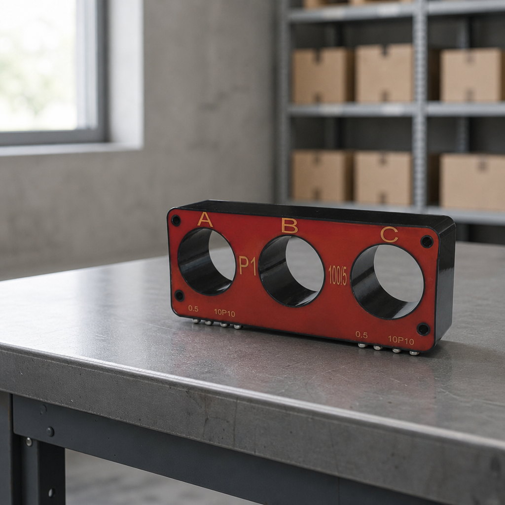
A three-phase combined current transformer is one cast body that carries a current transformer core for each of the three phases, so a single unit measures A, B and C instead of three separate single-phase units. Most designs add a fourth core, or an open construction, for zero-sequence (earth-fault) sensing, which is why one compact block can feed metering, protection and control. It is the standard way to instrument a pole-mounted switch or a ring main unit, where there is no room behind the panel for three individual transformers.
That choice is usually made early and then stays with the project, because it fixes the bushing spacing, the wiring loom and the protection scheme at the same time. This guide covers what the device is, where it fits, how the cores are configured, how to size the windows against the real conductor, and what a specification should state.
Specifying a combined transformer for a switch order?
Send us the switch or ring main unit you are instrumenting, the conductor size and the protection scheme. We will confirm the ratios, cores and mounting that match the primary circuit you already have.
What Is a Three-Phase Combined Current Transformer?
It is a current transformer assembly in which the magnetic cores and secondary windings for all three phases are vacuum-cast into a single epoxy-resin body instead of being built as three independent units. Each phase keeps its own window, core and secondary terminals, so the electrical function matches a three phase current transformer set — the difference is mechanical integration, not measurement principle. That is also why the device is usually described by its application rather than its construction: a unit sold for outdoor pole-mounted switches has its windows spaced to sit over the three-phase bushing, so the switch's own primary conductor becomes the primary winding.
The construction detail that matters commercially is the casting. Casting cores, windings and terminal blocks into one resin block removes the moisture path that gradually degrades a taped or paper-insulated assembly, and it removes the alignment work three separate units require on the production line.
Why Put All Three Phases in One Casting?
Three practical reasons: space, core matching and handling. A pole-mounted switch has internal clearances set by the insulation distance between phases, not by a wish to house extra equipment, so fitting three conventional transformers plus a separate zero-sequence transformer inside that envelope is often impossible — a combined block sits outside the bushing plane instead, where there is room. Core matching is the second reason: three separate transformers produce a phase-to-phase error that depends on how closely those units behave, whereas cores produced as one batch and cast in one body are magnetically similar by construction. Handling is the third: one block instead of three in the same enclosure.
Where Does a Combined Three-Phase Unit Fit?
- Pole-mounted switch assemblies. The transformer fixes over the three-phase bushing of an outdoor circuit breaker or recloser and supplies measurement, protection and often control power. Pole-mounted reclosers use internal or external current transformers and voltage sensors to feed their control — the arrangement G&W Electric describes in its own explanation of pole-mounted reclosers.
- Ring main unit and gas-insulated switchgear bushings. A unit on the incoming or outgoing three-phase bushing feeds current measurement, energy metering and the protection relay without occupying cable-compartment space.
- Busbar and cable compartments. Open or bar-type construction closes around an existing conductor, so the primary circuit does not have to be cut.
- Retrofit work. For the same reason, an open unit is one of the few instrument-transformer solutions that can be added to an installation already in service.
Combined Unit or Three Separate Single-Phase CTs?
| Three separate single-phase CTs | One combined three-phase CT | |
|---|---|---|
| Space in the switch body | Three mounting positions, plus a fourth for zero-sequence sensing; often will not fit | One block on the bushing or busbar plane |
| Core matching across phases | Depends on ordering matched units and on how they are stored and handled | Cores cast together in one batch, so behaviour is similar by construction |
| Primary circuit | Conductor is threaded through each unit separately | All three conductors pass through one plane; open versions close around an existing conductor |
| Wiring and terminal work | Three sets of terminations and three cable runs to dress | One terminal block, one loom, fewer connections to test |
| Zero-sequence sensing | Residual connection of the three secondaries, or a separate core-balance CT | Additional core in the same casting, or an open construction used as the zero-sequence element |
| Replacement and spares | One phase can be changed on its own | The whole unit is changed; one spare part number instead of three |
| Best fit | Panel switchgear with space behind the panel, and single-phase feeders | Compact pole-mounted assemblies, RMUs and retrofit work |
How Do You Read the Core Configuration?
A combined transformer usually carries more than one core per phase, because metering and protection want different things. Metering wants accuracy at normal load and a guaranteed limit on how far the secondary current can rise if something goes wrong on the primary side; protection wants a defined behaviour during a fault, including controlled saturation. Separate cores in the same window, each with its own class and burden, satisfy both.
| Metering core | Protection core | |
|---|---|---|
| What it is for | Billing, indication and measurement | Overcurrent and earth-fault protection |
| Behaviour at fault current | Output is limited so connected meters are not damaged | Must reproduce the fault current up to a stated multiple of rated current |
| What the class tells you | Accuracy over the rated current range, with its limit factor | Composite error, and the accuracy limit factor that fixes the multiple |
| What to check in the datasheet | Class, rated burden and rating factor | Class, accuracy limit factor and rated burden |
The published data for the LSY107-10 shows the pattern: a metering core and a protection core marked on the casting, offered across a ratio range from 20/1 to 600/5. The recognised reference for specifying current transformers is IEC 61869-2, Instrument transformers – Part 2: Additional requirements for current transformers, alongside IEC 61869-1 for general requirements. Name the standard, and the edition where your utility insists on it, in the RFQ, and ask the supplier to state which standard and edition the unit's type-test evidence refers to — a measured value without an edition behind it cannot be checked.
How Do You Size a Combined CT Against the Primary Conductor?
Sizing is a sequence, and the window comes before the electrical data:
- Interphase spacing first. Measure the distance between the three primary conductors on the actual switch or bushing arrangement. If the openings do not line up with the conductors, nothing else about the unit matters. Published dimensions — the 107 mm three-phase hole spacing and 320 × 127 × 65 mm body of the LSY107-10, or the 484 × 65 mm span of the open-type LSZJ1-10 — let you check this against a drawing before you commit.
- Conductor and window size. The primary must pass through the window with insulation and glanding clearances intact; check the bar or cable diameter rather than the nominal cross-section printed on the order. Centring matters, because a conductor pushed against one side of the window distorts the field and the ratio.
- Ratio, then secondary current. Choose the ratio so normal load sits in the upper part of the range while the maximum expected load stays inside it, then decide 1 A or 5 A secondaries — a wire-length and burden decision as much as a preference, and one that interacts with the relay input you are feeding.
- Burden and class. Add the relay, meter, wiring and terminal losses in the secondary loop and compare the total with the rated burden at the class you chose. A class quoted without a burden is half a specification.
- Zero-sequence core, if required. Decide whether earth-fault detection comes from a residual connection of the phase cores, from a dedicated core in the same casting, or from the open construction itself. This changes the part number.
- Environmental and mechanical fit. Confirm orientation, mounting holes and terminal-cover clearance against the enclosure lid, and confirm the insulation and surface condition suit the site's outdoor or pollution exposure.
Get the first two steps wrong and the project buys a transformer that cannot be installed; get the last three wrong and it installs, then fails a commissioning test or produces a ratio error nobody can explain.
What Is an Open-Type Three-Phase Current Transformer For?
An open-type, or split, transformer is built to be closed around conductors that are already in place: the magnetic circuit opens, the unit is positioned around the three-phase conductors, and the circuit is closed and clamped, so nothing has to be disconnected. That makes open construction the usual choice for retrofit and for zero-sequence duty, where all three conductors pass through the combined window together and the core responds to the sum of the three currents rather than to any single phase. Its published ratio range is correspondingly narrower — for the LSZJ1-10, zero-sequence ratios from 20/1 to 300/5 — because the currents being detected are small compared with load current. Two catalogue details are worth carrying into an enquiry: the unit is cast in resin and described as busbar-type, so the clamping faces and closure bolts are part of the accuracy, and an open unit used for zero-sequence sensing is not interchangeable with a closed combined unit used for the same function.
How Does the Sum of Three Phase Currents Detect an Earth Fault?
In a healthy three-phase circuit the three phase currents sum to zero, so the current that appears when they no longer sum to zero is the earth-fault current. There are two ways to obtain that quantity from current transformers, and the difference between them sets how small a fault you can detect.
The first is the residual connection: the three phase secondaries are connected so the relay sees the vector sum of the three currents. It costs nothing extra in hardware, but its sensitivity is limited by how closely the three cores behave. The second is a core-balance or dedicated zero-sequence core: all phase conductors pass through one core, so the flux is proportional to the sum alone. Being a single core rather than three, it is more sensitive and is used where the fault current is deliberately limited, for instance by a neutral earthing resistor or on a resonant-earthed system.
Both methods are legitimate and neither is automatically required. An engineering knowledge-base discussion of earth-fault sensing for medium-voltage systems compares residual connection of three phase CTs, core-balance or ring CT, open-delta voltage detection and grounding-branch current measurement, and notes that the choice should follow the maximum ground-fault current the earthing arrangement allows, the feeder CT ratio and accuracy, and the required pickup. That is the study to demand before the part number is frozen. Where the scheme is differential, the principle is formalised in the relay: restricted earth fault protection detects the difference between the residual current at the neutral earthing point and the residual current at the three-phase output, as Schneider Electric's description of the ANSI 64REF function sets out — and one combined transformer feeding both points from a single casting keeps those residuals more comparable than two separately sourced sets would.
One caveat applies to both methods. Sensitivity is a system property, not a product property: an excellent low-ratio zero-sequence core will still be insensitive if the secondary wiring, the relay pickup and the earthing arrangement have not been coordinated with the fault current the network can actually produce. Prove the scheme by injection, and where practical by a primary test through the complete circuit, before energisation.
What Should a Three-Phase Combined Current Transformer Specification State?
A specification that names only the ratio and the class leaves the manufacturer to guess at the geometry, and the guess is what causes late redesigns. State the following, in this order:
- Application and equipment — pole-mounted switch model, ring main unit or busbar compartment, with the drawing reference and the bushing or bar spacing.
- Conductor data: bar dimensions or cable type, conductor material, and the insulation diameter that must pass through the window.
- Ratios and secondaries for every core, phase by phase where the phases differ, with the zero-sequence ratio where a dedicated core is required.
- Class, burden and rating factor (or accuracy limit factor) for each core, with the secondary wiring length if burden is likely to be a constraint.
- Standard and edition the equipment is to be type tested against, and the test evidence the supplier must submit with the offer.
- Installation, environment and documentation: indoor or outdoor, mounting orientation, terminal-cover clearance, the pollution or humidity condition at site, and the dimension drawing, terminal marking, ratio and polarity test record and nameplate data you expect — as a controlled drawing revision, not a catalogue picture.
A supplier who will not put the core configuration and the standard edition in writing is the wrong supplier for a utility project, however competitive the number.
Installation and Commissioning Checks That Catch Most Faults
- Ratio and polarity, phase by phase. Test each core against the drawing rather than assuming the phases were wired in order. A reversed core in a residual connection changes the earth-fault behaviour of the whole scheme without any obvious symptom at load.
- Correct core on the correct function. Confirm that the metering core feeds the meter and the protection core feeds the relay; swapping them turns a defined protection performance into an unpredictable one.
- Secondary earthing and continuity. Check that the secondary circuit is earthed where the scheme requires and that no core is left open-circuit — an open secondary on a live transformer develops dangerous voltage across the terminals.
- Centring, closure and measured burden. Verify that each conductor is centred in its window and that an open unit has been closed and clamped to the manufacturer's instruction, then measure the secondary loop where the relay or meter is burden-sensitive instead of adding up catalogue figures.
- Proof of the earth-fault function. Inject the minimum earth-fault current you expect the network to produce and confirm the relay operates. That single test separates a scheme that was designed from one that was merely assembled, and it is the last chance to catch a residual connection wired in the wrong order.
Frequently Asked Questions About Combined Current Transformers
What is a combined current transformer?
It is a single cast-resin assembly that contains a current transformer core and secondary winding for each of the three phases, so one unit measures A, B and C. It may also carry a fourth core, or use an open construction, for zero-sequence or earth-fault sensing. The measurement principle is the same as three separate single-phase current transformers; only the mechanical integration differs.
Where are combined current transformers used?
Typically on pole-mounted switch and recloser assemblies, and on the incoming or outgoing bushings of ring main units and gas-insulated switchgear, where the three-phase conductor plane is accessible and space behind the panel is limited. Open and bar-type versions are also used in busbar and cable compartments, including retrofit work on existing installations.
What is the difference between a combined current transformer and an open-type one?
A combined transformer is normally a closed body with three windows or bushings that the primary conductors pass through. An open-type transformer has a magnetic circuit that can be opened and closed around conductors already in place, which is why it is preferred for retrofit work and for zero-sequence duty, where all three conductors must pass through a single core.
How do I choose between a combined unit and three separate single-phase CTs?
Decide on available space, on how closely the three phases must match, and on how you want to handle spares. A combined unit saves space, is cast from matched cores, and needs one wiring loom. Three separate units let you replace a single phase, and suit panel-type switchgear that has room behind the panel.
How do you size the windows against the primary conductor?
Start from the interphase spacing of the switch or bushing arrangement, and from the diameter of the conductor or cable that must pass through each window including insulation and glanding clearance. Only then fix the ratio, the secondary current, the class and the burden. Published hole spacing and overall body dimensions are what you check against the layout drawing.
Does a combined current transformer detect earth faults?
It can, if the design includes a zero-sequence core or if the three phase cores are connected in residual. A residual connection works from the vector sum of the three phase currents and is limited by how closely the cores behave. A single core-balance or zero-sequence core, through which all three conductors pass, is more sensitive and suits systems where the fault current is deliberately limited. Prove the chosen scheme by injection testing.
What should an RFQ or specification state?
State the equipment being instrumented with its drawing reference, the interphase and conductor dimensions, the ratio and secondary for every core, the class with its burden and rating factor, the zero-sequence requirement, the standard and edition to be type tested against, the indoor or outdoor environment, and the documentation you expect with the offer.
Can a combined current transformer be retrofitted to an existing installation?
Yes, in the open or split construction. The unit is positioned around the existing three-phase conductors and then closed and clamped, so the primary circuit does not have to be disconnected or re-terminated. Confirm the clamping arrangement and closure method with the manufacturer before the outage, and treat re-opening a closed unit in the field as a factory question rather than a workshop procedure.
Sources and further reading
- G&W Electric — Recloser on Pole Fundamentals: how pole-mounted reclosers work and how their CTs and voltage sensors feed the control
- NOJA Power — Recloser Fundamentals: three-phase recloser voltage range and the C37.60 / IEC 62271-111 recloser standard
- Schneider Electric — restricted earth fault protection (ANSI 64REF) and how the residual currents are compared
- Industrial Monitor Direct — selecting sensitive earth-fault protection for medium-voltage systems: residual connection versus core-balance CT
- IEC TR 62271-321 — the IEC publication whose bibliography lists the IEC 61869 and IEC 62271 part titles and editions referenced above
Note on sources: the product data quoted here — the 107 mm hole spacing, 320 × 127 × 65 mm body and 20/1 to 600/5 ratio range of the LSY107-10, and the open-type LSZJ1-10 with its 20/1 to 300/5 zero-sequence range and 484 × 65 mm span — comes from Nahu Group's own published product data. No price, delivery time or certification claim is made.
Nahu Group (NAHU Electric Technology) manufactures the combined transformers described above, together with voltage transformers, metering boxes and the 10–35 kV distribution equipment they are fitted to. The specialty and busbar transformer range covers both the closed combined family and the open-type construction, and the current transformer range covers the single-phase units used where a combined block is not the right answer. For related reading, the bushing current transformer guide explains the window-type principle in detail, the split-core guide covers the open magnetic circuit these units share with retrofit solutions, and the neutral current transformer guide compares the residual and core-balance options.
Published September 30, 2026 · Nahu Group (NAHU Electric Technology)