
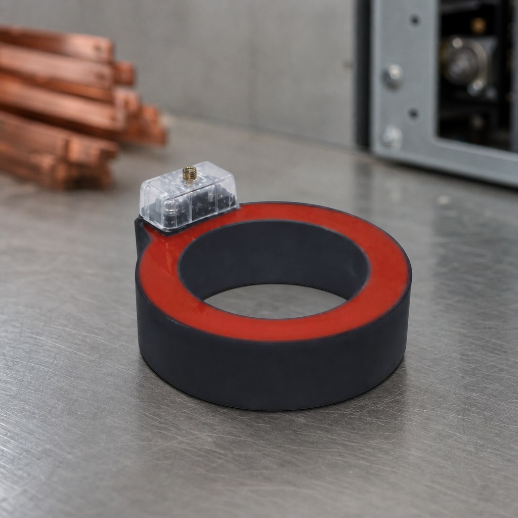
A bushing current transformer is a window-type current transformer with no primary winding of its own: its toroidal core and secondary winding are mounted around a bushing, or around a cable, so that the primary conductor passing through the opening acts as a single-turn primary. Mounting it over an existing bushing or cable end saves panel space and, on the openable designs, allows the CT to be fitted without dismantling the primary circuit. It is the standard solution for feeder metering and protection on transformers and switchgear, where a wound-primary CT would be too large.
The consequences of that construction are what make this a specification topic rather than a catalogue lookup. A CT with no primary winding has its accuracy, its saturation behaviour and its ratio all tied to the geometry of something the CT manufacturer does not build — the bushing or the cable that passes through it. This guide covers how the construction differs from a wound-primary CT, how to size the bore and the ratio, what the accuracy classes actually promise, and what to ask a supplier for.
What Is a Bushing Current Transformer?
The definition is a construction definition. A bushing CT "is a window-type current transformer mounted around the bushing's flange", consisting "only of a toroidal-shaped core with a secondary winding", in which "the bushing's centre conductor forms the single turn primary". It may sit inside a transformer tank, under the cover, or be mounted externally, and its secondary terminals and nameplate are brought out where they can be reached — commonly into the transformer's control cabinet.
Because the primary is whatever passes through the window, the CT itself is a passive ring. That is the source of both its advantages and its limits:
- Compact. No primary winding means a small, flat unit that occupies the space a bushing already has.
- Self-centring on a bushing. Slipping the ring around a bushing automatically places the primary conductor in the middle of the window — the position of maximum accuracy.
- Ratio fixed by turns, not by choice. The ratio follows the secondary winding and the tappings provided; more than one ratio is obtained by tapping the secondary at increments along the winding.
- Sensitive to what the site does with the conductor. Cable routing, return conductors and window fill all change the measured result.
Bushing CT vs Wound-Primary CT: Which Do You Need?
The alternative to a window-type CT is a wound-primary CT, whose primary consists of a few turns of heavy conductor capable of carrying the full load current, with many turns of smaller wire on the secondary. Manufacturer handbooks draw the practical difference out clearly.
| Window / bushing type | Wound-primary type | |
|---|---|---|
| Primary winding | None — the conductor passed through the opening is the primary, one pass being one turn | A few turns of heavy wire sized for the full load current |
| Secondary | Distributed on a low-leakage toroidal core | Many turns of smaller wire, typically rated 5 A or 1 A |
| Where it is fitted | Over a bushing, a busbar or a cable, including retrofit onto an installed cable | In its own enclosure, in series with the primary circuit |
| Leakage reactance | Low and predictable, because the secondary is fully distributed | Higher and less predictable, because the winding is not fully distributed |
| How accuracy is established | By calculation for the bar and window constructions | By test, since leakage reactance cannot be calculated reliably |
| Usual application | Feeder and bushing metering and protection; retrofit where the circuit cannot be opened | Low-ratio, high-burden duties and applications needing a defined primary winding |
One practical advantage of the window construction deserves spelling out, because it decides feasibility rather than accuracy. On an openable cable CT, the cable enters through the opening in the transformer, and because of the openable construction the CT can be installed even after the cable and its terminator are already connected. Where a project needs metering on an existing feeder without an outage, that is not a convenience — it is the only workable route.
How Do You Size the Bore and the Ratio?
Bore and ratio are chosen together, and neither can be settled before the primary conductor is known.
The bore must clear the bushing or cable it goes over, with the conductor sitting inside the window rather than against its edge. Manufacturers publish bore options for exactly this reason. Nahu Group's bushing-type range, for example, is offered with Ø82/Ø130 and Ø45/Ø100 bore variants, so that the same electrical design covers different bushing and cable diameters. Provide the supplier with the diameter over the insulation or over the bushing and the answer follows.
The ratio is then read off the published range, which for this construction is typically expressed as primary-to-secondary notation from low ratios upwards — 100/1 being a low-ratio example in the range. Two decisions drive the choice:
- What the relay or meter needs to see. Metering and protection have different requirements; if the duty is heavy earth-fault detection, start from the sensitivity the protection needs and work back to the ratio.
- The 1 A or 5 A secondary. The secondary rating changes the burden arithmetic and the wiring cross-section, and it must match the connected device.
The available class ranges tell you what the unit is intended for. Published data for one bushing-mounted family lists measuring classes of 0.2S, 0.2 and 0.5 and protection classes from 10P10 to 10P20, with measuring, protection or double-winding versions. A double-winding unit carrying a metering core and a protection core in the same ring is a common answer where panel space is the constraint.
What Do 0.2S, 0.5, 10P10 and 10P20 Actually Promise?
The class number is a promise made at a stated burden, not a blanket accuracy figure. That sentence is the whole subject.
For a protection CT, "the accuracy class is designated by the highest permissible percentage composite error at the rated accuracy limit primary current prescribed for the accuracy class concerned, followed by the letter P". The number after the P is the rated accuracy limit factor — the ratio of the rated accuracy limit primary current to the rated primary current. A 10P20 is therefore a 10 % composite error class with an accuracy limit factor of 20: it stays within its stated error up to twenty times rated primary current, which is what makes the class usable for fault detection.
For a metering CT, the class number is a percentage ratio error at rated current — the 0.2S, 0.2 and 0.5 families used in billing and load measurement. Those classes are far tighter than the protection classes, and they are the classes that have to be defended against burden and against low-current performance.
Burden is where the promise gets qualified. Burden is the secondary load, named separately from the primary load to keep the two apart, and it is stated in volt-amperes or ohms: "the burden rating indicates the amount of resistance (in ohms) and inductance (in milli-henries) which may be connected to its secondary without causing a metering error greater than specified by its accuracy classification". The same handbook states the consequence directly — accuracy is dependent on the burden.
That dependence is not a small correction in service. The actual accuracy limit factor "differs from the rated accuracy limit factor and is proportional to the ratio of the rated CT burden and the actual CT burden", so a CT asked to drive more secondary load than its nameplate assumes loses protection performance, and the distortion of a saturated CT "may endanger the operation, selectivity and co-ordination of protection". Where a relay's own application manual is consulted, the point appears as a design duty: check the class and the accuracy limit factor against the protection scheme rather than against the previous project's specification.
Why Does Centring and Window Fill Matter?
A window-type CT measures the current that passes through its opening, and only that current. Two site conditions corrupt that measurement, and both are visible on a walked-down installation.
- Position of the primary conductor. Accuracy depends on where the conductor sits inside the aperture — the primary conductor should be centred in it. This is why a bushing-mounted ring is an engineering advantage: mounting over a bushing "automatically centers the conductor inside the CT window".
- Return paths through the window. If a cable's metal armour or a protective conductor is drawn through the transformer, the effect of the current in them on the sum of the phase currents has to be eliminated when the CT is installed. Left in, they add or subtract from the measured sum and quietly bias an earth-fault measurement.
- Mechanical stability. The ring must stay where it was set. A CT that can shift on its mounting will not keep the centring it was designed around.
Adding burden and primary current rating to that list gives the two operating limits that must not be crossed: the burden impedance should not exceed the specified maximum, and the primary current rating should not be exceeded, because the core may enter its non-linear region and ultimately saturate.
Saturation and Remanence: Why Protection CTs Age Differently
Saturation is undesirable whether the CT is used for protection or for metering. In saturation, the secondary output current "is no longer a miniaturized replica of the primary current but rather a distorted version with a lower than expected amplitude", and the practical consequence is a protection system that may misoperate.
Remanence is the second-order problem. If the core retains excessive residual magnetism it will saturate sooner than expected, and remanence flux is dissipated very little in service — removing it requires demagnetisation of the core. A CT that has seen several fault clearances may therefore behave differently from the same CT when it was commissioned, which is why bushing CT condition assessment includes ratio and phase analysis, a saturation test, a residual magnetisation check with demagnetisation, winding resistance and a burden test.
Transient performance is the formal version of the same concern. Current transformer standards define protection classes for transient performance, and distinguish a class with a remanent flux limit — a class in which the saturation behaviour under symmetrical short-circuit is specified. If a protection scheme depends on faithful reproduction of the DC component of an offset fault current, that requirement belongs in the specification, not in the commissioning checklist.
What Should a Bushing Current Transformer Specification State?
- Voltage class and system earthing, and the rated frequency
- Rated primary and secondary currents, with the ratio tappings required
- Accuracy class and rated output (burden) for every core — separately for the metering core and the protection core on a double-winding unit
- Accuracy limit factor for the protection core, and any transient performance requirement
- Bore diameter, and the diameter over the bushing, cable insulation or screen it must clear
- Insulation level and whether the unit is for indoor or outdoor service
- Mounting arrangement, terminal accessibility and the position of the nameplate
- The standard and edition the CT is manufactured and type-tested to, with the type-test report for the exact model
Add the two questions that are easy to forget. First, whether the CT must be installed over an already-terminated cable — that decides between a solid ring and an openable one. Second, what the connected burden will actually be at commissioning, because the class on the nameplate is a conditional statement about a burden the site has to honour.
Common Specification Mistakes
- Choosing the ratio before the bore. A ring that will not go over the bushing or cable cannot be made to work by changing the ratio.
- Quoting a class without a burden. An accuracy class without its rated output is not a specification.
- Ignoring the return conductor. Armour or protective conductors left passing through the window corrupt the measurement they were meant to improve.
- Assuming a double-winding unit shares one accuracy. Metering and protection cores are specified, and tested, separately.
- Commissioning only the ratio. Without a saturation, burden and remanence check, a CT can pass a ratio test and still misoperate a relay.
Frequently Asked Questions About Bushing CTs
What is a bushing CT?
It is a window-type current transformer mounted around a bushing or a cable. It has no primary winding of its own: the core and secondary winding form a ring, and the conductor passing through the opening acts as the single-turn primary.
How is a bushing CT different from a wound-primary CT?
A wound-primary CT has its own primary winding of heavy conductor, sized to carry the full load current, and is usually built into its own enclosure. A window-type unit has no primary winding, is smaller, and fits over a conductor that is already there. Because a wound primary cannot have its leakage reactance calculated reliably, its accuracy is established by test, while window and bar constructions can be calculated.
What does the second number in 10P20 mean?
It is the rated accuracy limit factor — the ratio of the rated accuracy limit primary current to the rated primary current. A 10P20 is therefore a class 10P unit with an accuracy limit factor of 20, meaning it holds its stated error up to twenty times rated primary current.
How do I choose the bore size?
The bore must clear the bushing or cable it is fitted over, with the primary conductor centred inside the window rather than against its edge. Give the supplier the diameter over the bushing, or over the cable insulation or screen, and the bore follows from that.
Does burden affect accuracy?
Yes. The accuracy class is stated at a rated output, and the effective accuracy limit factor is proportional to the ratio of the rated burden to the actual burden. Exceeding the specified maximum burden impedance can drive the core into saturation, which distorts the secondary current and can cause protection to misoperate.
Can a bushing CT be fitted without an outage?
On the openable designs, yes. Because the transformer opens, it can be installed even after the cable and its terminator are already connected. A solid ring has to go over the conductor during assembly, so it cannot be added to a finished cable end.
What is remanence, and why does it matter?
Remanence is residual magnetism left in the core. A core with excessive remanence saturates sooner than expected, and the flux dissipates very little in service, so removing it requires demagnetisation. That is why a unit that has cleared several faults can behave differently from the same unit when it was commissioned.
Can one unit serve metering and protection at the same time?
Yes, in a double-winding version that carries a metering core and a protection core in the same ring. The two cores are specified and tested separately, so the accuracy class and the rated output must be stated for each.
Sources and Further Reading
- IEC 61869-2:2012 — Instrument transformers, Part 2: Additional requirements for current transformers — the governing standard for inductive current transformers, applicable from 15 Hz to 100 Hz
- Instrument transformer basic technical information and application (GE Vernova, Grid Solutions) — the definition of burden, and the wound versus window/bar construction comparison
- Transformer bushing CTs (Megger) — the definition of a bushing CT, saturation and remanence, and the diagnostic tests listed above
- Cable current transformer installation instructions (ABB, KOLMA) — installation over an already-terminated cable, and the return-conductor requirement
- Current transformer requirements for non-directional overcurrent protection (ABB application note) — how actual burden changes the effective accuracy limit factor, and the consequence of saturation
A bushing CT is the cheapest way to put accurate measurement and protection onto a bushing or a cable, and it is also the CT whose performance depends most on decisions taken outside the CT. Fix the bore against the real conductor, state the class together with the burden, keep the return paths out of the window, and commission the core rather than just the ratio. None of those four steps costs anything, and each of them prevents a failure mode that a nameplate cannot show.
Nahu Group (NAHU Electric Technology) manufactures bushing-type current transformers with measuring, protection and double-winding versions, alongside its voltage transformers, split-core and through-core current transformers, metering boxes and 10–35 kV switching equipment. See the specialty range, compare constructions in the split-core current transformer guide, or read how to choose a current transformer ratio before fixing a ratio for a project.
Published September 29, 2026 · Nahu Group (NAHU Electric Technology)