
A switchgear test list has two halves that answer two different questions. Factory routine tests prove the assembly was built the way the type-tested design was approved; site acceptance tests prove that transport, foundation work and cable termination did not undo it. The mistake buyers make is treating the first as paperwork and the second as a formality — the failures that delay energisation almost always sit in the gap between them.
IEC 62271-200 is the reference for the assembly, IEC 62271-1 for the common clauses, and every item below should appear in the submittal with a value, a judgement criterion and a signature. An item without a criterion is not a test; it is an observation.
Factory Routine Tests: What Must Be Proven Before Dispatch
Routine tests are performed on every unit, not on a sample. For a metal-enclosed or metal-clad assembly the list below is the minimum a buyer should see in the factory test report, with the measured value recorded against each item.

| Test | Purpose | Judgement on the report |
|---|---|---|
| Power-frequency dielectric test, main circuit | Proves insulation clearances and busbar support insulation survive the specified voltage | Applied voltage and duration (1 min) stated; no breakdown or flashover; test voltage matches the rated insulation level |
| Dielectric test, auxiliary and control circuits | Finds wiring damage and clearance faults in the secondary | Voltage applied to the whole auxiliary circuit, wiring disconnected from sensitive devices where required |
| Main circuit resistance | Finds loose joints, undersized contact pressure and bad busbar connections | Value per phase in micro-ohms, compared with the type-test or design value; phase-to-phase spread within the stated tolerance |
| Mechanical operation test | Proves the mechanism, interlocks and indicators work after assembly | Number of close/open cycles stated; interlocks demonstrated, not just present |
| Wiring and secondary continuity | Catches wrong terminal numbers and crossed cores before they become commissioning faults | Point-to-point check against the approved schematic, signed by the tester |
| Instrument transformer ratio and polarity | Confirms the CT and VT match the rating plate and the drawing | Measured ratio and polarity per core; metering and protection cores clearly separated |
| SF6 tightness and gas density | Detects seal defects that would otherwise surface after energisation | Leakage expressed per the standard method; density switch alarm and lockout settings recorded |
| Partial discharge, where specified | Finds insulation defects that a withstand test leaves alive | pC value with the pre-stress voltage stated; a pC number without a voltage means nothing |
| Protection relay settings and injection | Confirms the relay is set to the study and trips the right breaker | Setting sheet revision, injection results per stage, trip and alarm contacts verified |
Two items on that list are frequently subcontracted and then reported as if they were done in-house: partial discharge and relay injection. Ask which laboratory performed the test and see the calibration certificate for the instrument. Where the breaker itself is tested — timing, travel, vacuum integrity — the sequence is set out in the vacuum circuit breaker testing procedure, and the cores behind the ratio figures are described on the current transformer range.
What Each Factory Test Actually Detects
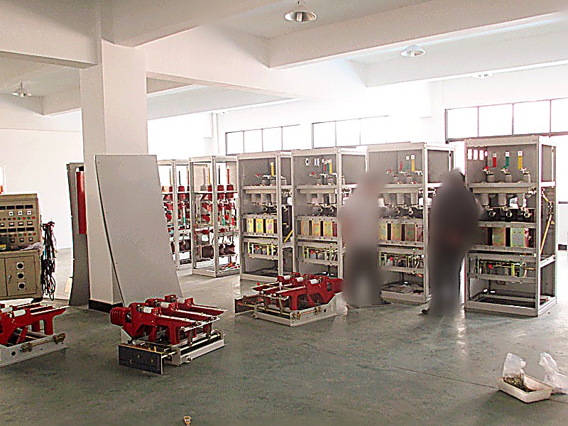
A test list is only useful if the buyer knows which defect each item catches. Otherwise a report full of "OK" tells you nothing about the unit you are about to energise.
| Defect | Test that finds it | What it costs if missed |
|---|---|---|
| Metal particle or void left in cast resin | Partial discharge | Flashover weeks after energisation, with the feeder out and the unit to be replaced |
| Loose busbar joint or under-torqued contact | Main circuit resistance | Hot joint, thermal damage, unplanned outage in the first summer |
| Wrong CT ratio or reversed polarity | Ratio and polarity test | Protection misoperates or metering under-reads for years |
| Interlock that blocks the wrong operation | Mechanical operation and interlock test | Operator works around the interlock, or cannot restore supply after a fault |
| Damaged secondary core during wiring | Auxiliary dielectric and continuity | Trip circuit fails on the one operation that matters |
| Slow SF6 leak at a seal | Tightness test | Gas top-ups and a lockout at the worst moment; possible derating |
Site Acceptance: What Changes Once the Unit Is Installed
On site the unit has been transported, lifted, bolted to a foundation, connected to cables and had its secondary wiring run to a panel. Each of those steps can undo a factory result, so the site list tests the interfaces rather than repeating the factory.
| Site test | What it proves | Judgement criterion to write down |
|---|---|---|
| Visual and mechanical inspection | The unit arrived intact and is installed as drawn | No transit damage, correct clearances, gland plates and cable boxes sealed, torque marks intact |
| Insulation resistance, main circuit | No moisture, dust or cable-termination damage | Value recorded per phase against the delivery value and the utility minimum; a large drop between visits is the finding |
| Insulation resistance and continuity, secondary | Wiring survived the pull and the terminations are sound | Continuity per core, no cross-connection, IR above the figure agreed with the utility for control wiring |
| CT and VT secondary checks | The instrument transformers still match the drawing after cable work | Ratio and polarity re-checked at the terminals that feed the relay and the meter |
| Protection injection at the panel | The complete trip path works, not just the relay | Relay picked up, trip coil operated, breaker tripped, alarm and event recorded with timestamps |
| Interlock and earthing switch operation | The safety mechanism works in the installed condition | Every blocked operation demonstrated as blocked; earthing switch closed and opened with the correct status indication |
| Gas density and dew point, SF6 units | The gas system is sound after transport and top-up | Pressure and dew point within the manufacturer's filling values, alarm and lockout verified by simulation |
| Cable tests where specified | The cable and its terminations, not the switchgear, are sound | Test method, voltage and duration per the cable standard; results kept with the switchgear record |
How to Write a Judgement Criterion That Holds Up
Most disputes at inspection are not about whether a test was done but about what number was acceptable. Three rules make a criterion defensible: tie it to a reference the supplier cannot move (the type test report, the standard clause or the utility specification), state the condition under which the value applies (temperature, pre-stress voltage, test duration), and say what happens when the value is missed — retest, replace or accept with a deviation.
- For dielectric tests, quote the rated insulation level from the type test report rather than a remembered figure.
- For resistance and insulation measurements, record the ambient and the instrument, because both change the number.
- For partial discharge, state the pre-stress voltage and the pC limit together; the pair is the criterion, not either alone.
- For protection, state the injection point — relay terminals or primary — because the two prove different things.
Where partial discharge matters, the interpretation is a subject in itself; the partial discharge testing guide explains what the measurement actually shows and where it is misread.
Where Test Lists Fail at Inspection
- Values without conditions. An insulation resistance figure with no temperature and no instrument cannot be compared with anything, including the same unit next year.
- Reports without serial numbers. If the report does not carry the unit serial and the drawing revision, it proves nothing about the equipment delivered.
- Copied type-test values in a routine report. Identical numbers across several units are a warning sign, not reassurance.
- Interlocks "checked" by inspection only. The interlock has to be operated and shown to block the wrong action.
- Arresters and instruments left connected during insulation tests. The reading is then a statement about the arrester, not the switchgear.
- No record of who tested and when. An unsigned report is not evidence, and a warranty claim without evidence is a negotiation you lose.
What to Ask For With the Equipment
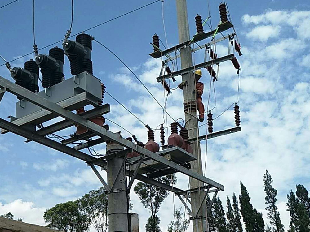
The document set is part of the specification, not an afterthought. For a medium voltage assembly, the distribution cabinet range is configured to order, so the documents should be listed in the same enquiry as the ratings:
- Type test report to IEC 62271-200, with the certificate body and the tested configuration identified — the type test report guide covers how to read it.
- Routine test report per unit, with serial numbers, measured values, instrument identification and tester signature.
- Interlock function record and the approved schematic revision it was checked against.
- Protection setting sheet and injection record, with the study revision quoted.
- Gas filling values and dew point, plus the density switch settings, for SF6 assemblies.
- Outline and foundation drawings, cable entry details, and the earthing terminal arrangement.
- Packing list and transit damage procedure, agreed before dispatch rather than after arrival.
Where Nahu Group Fits
Nahu Group builds medium voltage switchgear for 12 kV and 40.5 kV systems — metal-enclosed ring main units, armored metal-clad withdrawable gear and fixed panels — air insulated, for indoor substations and distribution rooms, with protection, metering and interlocking per the single line diagram. Each unit ships with its routine test record against the serial number.
To get a test plan matched to your specification, send the single line diagram, the system and highest system voltage, the fault level and duration, the protection scheme and the utility's acceptance clauses. We will return the routine test list, the site acceptance checklist and the document package index before the order is placed, so that nothing in the list arrives as a surprise at inspection. Breaker-level timing and travel records are covered under the vacuum circuit breaker range.
Frequently Asked Questions About Switchgear Testing
What is the difference between a routine test and a type test?
A type test is done once on a representative design to prove the design meets the standard; a routine test is done on every unit to prove it was built like the tested design. A routine test report without a type test behind it proves the unit works, not that it is qualified for the fault level and insulation level you specified.
Which tests must be repeated on site?
Only the ones that installation can invalidate: insulation resistance, secondary continuity, instrument transformer checks, protection injection, interlock operation and gas tightness. Repeating the full factory dielectric test on site is neither practical nor required; what matters is proving that transport, foundations and cable work did not damage what the factory proved.
What insulation resistance value is acceptable?
There is no single number that fits every assembly. The defensible criterion is a value agreed with the utility for the voltage class, compared with the value measured at delivery, with the temperature and instrument recorded. A reading that halves between two visits matters more than whether it sits above a threshold.
Does a partial discharge test replace the power-frequency withstand test?
No. The withstand test proves the insulation survives the specified voltage for a minute; the partial discharge measurement finds defects that survive that minute and then fail in service. They answer different questions, and a specification that asks for only one of them leaves half the insulation risk unmeasured.
How long should the test records be kept?
For the life of the equipment. The routine test values become the baseline for every later measurement, including the comparison that tells you whether a joint is degrading. Utilities normally keep them with the asset register, and a buyer who does not receive them at handover has lost the reference point permanently.
Sources and Further Reading
- IEC 62271-1:2017 — High-voltage switchgear and controlgear, Part 1: Common specifications — the family base standard: service conditions, rated quantities and the routine and type test schedule every assembly goes through.
- IEC 62271-200:2021 — High-voltage switchgear and controlgear, Part 200: AC metal-enclosed switchgear and controlgear for rated voltages above 1 kV up to and including 52 kV — defines the test classes for metal-clad and compartmentalised switchgear and what each certificate must show.
- IEC 62271-100:2021 — High-voltage switchgear and controlgear, Part 100: Alternating-current circuit-breakers — the interrupting and switching duties behind the short-circuit and capacitive line items on the test report.
Published Nov 6, 2026 · Nahu Group (NAHU Electric Technology)