
Partial discharge testing is a measurement of the small, localised electrical discharges that occur inside insulation without bridging it completely. The test applies voltage to the equipment, measures the charge that each discharge transfers, and compares the result with the limit set by the product standard. It is used because a discharge too small to trip a protection relay can still erode insulation until the equipment fails in service.
For medium-voltage switchgear, current transformers, voltage transformers and cable accessories, the test is one of the few measurements that looks directly at insulation quality rather than at whether the equipment merely survived a voltage. That is why it appears in factory routine tests, in type-test programmes and in site commissioning — and why a buyer who cannot read a partial discharge test report is accepting a number without knowing what produced it.
This guide explains what the test measures, how the measurement is made and calibrated, what a credible report contains, and which questions separate a meaningful result from a decorative one.
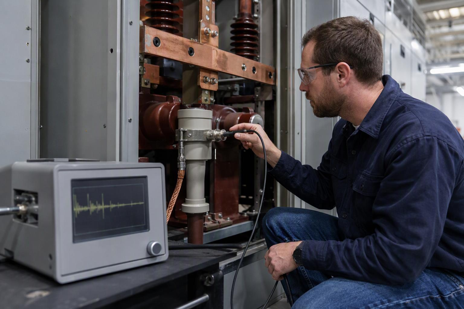
What Is Partial Discharge Testing?
IEC 60270 defines a partial discharge as a localised electrical discharge that only partially bridges the insulation between conductors, and which may or may not occur adjacent to a conductor. The definition matters because it separates partial discharge from two things it is often confused with: a full breakdown, which bridges the insulation and produces a fault, and corona, which the same standard describes as a form of partial discharge occurring in gaseous media around conductors remote from solid or liquid insulation.
Partial discharge begins where the local electric field is concentrated — a void inside cast resin, a sharp protrusion on a conductor, a metallic particle, a contaminated surface, or a low-density region in liquid insulation. Once the field is high enough, ionisation creates a streamer, and each streamer transfers a small amount of charge. The discharge extinguishes when the field collapses, then repeats on the next voltage cycle. The damage is cumulative: the discharge erodes the cavity wall, deposits decomposition products and eventually creates a conducting path.
The measurement is therefore not a check that the insulation is intact today. It is a check that the insulation contains no defect active enough to grow. A unit can pass a power-frequency withstand test and still discharge steadily at a level that will end its life early, because the withstand test only proves the insulation survived for one minute.
Why Does Partial Discharge Testing Matter More Than a Withstand Test?
A power-frequency withstand test answers one question: did the insulation hold at the test voltage for the test duration? It says nothing about what happens at operating voltage over twenty years. It answers a different question: is there a defect that is already discharging, and how large is the charge it transfers?
The practical consequences show up in three places:
- Factory quality — a casting void, a misplaced insert or a contaminated interface is a manufacturing defect. It is cheapest to find at the routine-test stage, before the unit is packed.
- Installation quality — cable terminations, separable connectors and busbar joints are assembled on site, often by a different crew from the one that built the switchgear. Partial discharge measurement is one of the few ways to verify that work before energisation.
- Condition assessment — for equipment already in service, a trend in partial discharge activity is an early warning that a maintenance intervention is due, rather than a post-mortem after a failure.
The measurement is sensitive to the test arrangement as well as to the insulation. A result is only comparable with another result when the test voltage, the measuring circuit, the bandwidth and the background noise level are all known. That is why the standard spends as much space on circuits and calibration as it does on limits.
What Does a Partial Discharge Test Actually Measure?
The quantity most often reported is apparent charge. IEC 60270 defines it as the charge which, if injected within a very short time between the terminals of the test object in a specified test circuit, would give the same reading on the measuring instrument as the partial discharge current pulse itself. Apparent charge is expressed in picocoulombs (pC).
The word apparent is doing real work. The charge measured at the terminals is not the charge dissipated inside the cavity; it is the charge that would produce the same instrument response. The relationship depends on the geometry of the defect and the capacitance of the test object, which is why a pC figure cannot be converted into a defect size without knowing the arrangement.
Three further quantities usually accompany the charge reading:
- Inception and extinction voltage — the voltage at which discharge starts as the voltage is raised, and the voltage at which it stops as the voltage is lowered. A large gap between the two indicates a defect that stays active well below the test level.
- Phase-resolved pattern — the distribution of pulses across the AC cycle. Because discharge pulses are nanosecond-scale events, they can be plotted against the 50 Hz or 60 Hz waveform. The resulting pattern helps identify whether the source is a void, a surface track or corona.
- Pulse repetition rate and amplitude trend — whether activity is steady, rising with voltage, or intermittent. Amplitude behaviour with voltage differs between cavities in solid insulation and discharges in gas or liquid.
Radio interference voltage is a related measurement, historically used on transformers and surge arresters. It is based on NEMA 107-1987 and uses a narrow 9 kHz bandwidth with a tunable centre frequency, reporting interference voltage in microvolts rather than charge in picocoulombs. A radio interference voltage result and an apparent charge result are not interchangeable, and a report should say which one was measured.
How Is Partial Discharge Measured in a Factory Test Bay?
The conventional method is an offline measurement made with an external voltage source, following one of the measuring circuits described in IEC 60270. The circuit has four functional parts: a blocking impedance between the source and the test object to reduce high-frequency interference from the supply; the test object itself; a coupling capacitor; and a measuring impedance that converts the discharge current into a voltage pulse for the detector.
Circuit choice changes sensitivity. With the measuring impedance in series with the coupling capacitor, sensitivity is moderate. Placing it in series with the earth connection of the test object raises sensitivity but exposes the impedance to damage if the test object breaks down. A bridge arrangement connected to the low-voltage side of the test object and the coupling capacitor reduces the effect of external electromagnetic disturbance. For transformers with capacitively graded bushings, the bushing tap can serve as the coupling capacitor.
Before any voltage is applied, the circuit is calibrated. A calibrator injects pulses of known charge, and the reading is used to establish the scale factor of the measuring system. The calibrator should sit as close as possible to the high-voltage terminals of the test object, because stray capacitance between the calibrator and the terminals introduces error. Calibration is not a formality: without it, the pC value has no defined meaning.
Bandwidth also matters. A wideband measurement according to IEC 60270 has historically used fixed lower and upper limit frequencies of 100 kHz and 500 kHz; an amendment in 2015 allowed the upper limit to extend to 1 MHz. Wider bandwidth captures more of the pulse energy but also admits more ambient noise, so the choice interacts with the shielding of the test bay.
How Is Partial Discharge Measured On Site?
On site, galvanic access to the high-voltage conductors is usually impossible without opening the equipment, and the ambient noise of a substation is far higher than in a laboratory. Non-conventional detection methods address both problems by sensing the effects of discharge rather than the charge at the terminals.
UHF sensors couple high-frequency signals from cable sealing ends, joints and terminations, from transformer drain valves, or from sensors installed inside gas-insulated switchgear. They are fitted at earth potential, which makes them safe to install on live equipment, and the strong attenuation of distant signals at UHF gives a favourable signal-to-noise ratio and localises the source. The trade-off is that a UHF reading is not an apparent charge in picocoulombs, so it cannot be compared directly with an IEC 60270 limit.
Acoustic and transient earth voltage methods are also used for survey work on metal-enclosed switchgear. They are valuable for locating a source and for ranking compartments, but they are screening tools. When a screening result is abnormal, the next step is a calibrated measurement or an offline test, not a decision based on the survey reading alone.
| What it measures | Typical use | Main limitation | |
|---|---|---|---|
| Conventional, IEC 60270 | Apparent charge in pC through a calibrated coupling circuit | Factory routine and type tests; offline site tests | Requires a voltage source and a low-noise environment |
| UHF sensing | High-frequency electromagnetic emissions from the discharge | GIS, cable joints and terminations, online monitoring | Reading is not an apparent charge; needs a baseline for comparison |
| Acoustic sensing | Sound emitted by the discharge | Locating a source inside a compartment | Attenuation and reflection make amplitude non-quantitative |
| Transient earth voltage | Voltage pulses on the enclosure surface | Rapid survey of metal-enclosed switchgear | Screening only; susceptible to external interference |
| Radio interference voltage | Interference voltage in microvolts, narrow bandwidth | Transformers and surge arresters | Different quantity from apparent charge; not interchangeable |
What Should a Partial Discharge Test Report Contain?
A report is only useful if another engineer could repeat the measurement from it. The following items are the minimum for that to be true:
- Identification of the test object, including serial number and the configuration tested
- The product standard and edition that supplied the limit, and the limit itself as written in that standard
- Test voltage, applied duration, and whether the voltage was raised in steps
- The measuring circuit used, the coupling capacitance and the detector bandwidth
- Calibration date and the charge used for calibration
- Background noise level before the test object was energised
- The measured apparent charge, and whether it was steady or rising
- Phase-resolved pattern or pulse record, not only a single number
- Ambient conditions — temperature and humidity — because surface discharge is humidity-sensitive
A report that gives only a pass mark and a pC figure is weak evidence. Without the background noise level, a low reading may simply mean the detector could not see the defect. Without the test voltage, a reading cannot be compared with any other reading. Without the calibration record, the unit of the number is unknown.
Partial Discharge vs Other Insulation Tests: What Each One Proves
Partial discharge is one of several insulation measurements, and buyers frequently treat them as substitutes when they are complementary.
| What it detects | What it cannot tell you | |
|---|---|---|
| Power-frequency withstand | Whether the insulation survives a defined overvoltage for a defined time | Whether a defect is discharging at operating voltage |
| Partial discharge measurement | Active defects: voids, protrusions, contamination, poor interfaces | Mechanical condition, contact wear, or remaining life in years |
| Insulation resistance | Gross conduction paths and moisture | Localised defects that do not bridge the insulation |
| Tan delta | Dielectric losses and their trend with voltage | The location of a defect, or small discharges below the loss sensitivity |
| Radio interference voltage | Interference level from discharge activity | An apparent charge value comparable with IEC 60270 limits |
What Are the Common Mistakes When Buying on Partial Discharge Data?
Most procurement errors are comparison errors rather than measurement errors. Five recur often enough to check for by name:
- Comparing pC values taken at different voltages. A reading at one test voltage says nothing about a reading at another, because discharge activity is voltage-dependent.
- Ignoring background noise. A reported value close to the noise floor is a statement about the test bay, not about the insulation.
- Accepting a screenshot instead of a record. A photograph of a display cannot be audited; a calibrated record with the circuit and settings can.
- Treating a UHF or acoustic survey as an apparent charge result. These methods detect and locate; they do not produce a pC value against an IEC 60270 limit.
- Assuming a type test covers every unit. A type test demonstrates a design; a routine test demonstrates the individual unit. Ask which one the report refers to.
Where Does Partial Discharge Testing Fit for Switchgear and Instrument Transformers?
For medium-voltage equipment the test appears at three different moments, and the three are not interchangeable. At the design stage, a type-test programme establishes that the design meets its product standard. At the end of the production line, a routine test checks each unit for manufacturing defects. After installation, a commissioning test checks the work that was done on site — terminations, connections and interfaces that were not part of the factory test.
The applicable requirement comes from the product standard, not from a generic figure. Instrument transformers and switchgear are covered by different IEC parts, each with its own test voltages and limits, and those limits are revised between editions. The correct question to a supplier is therefore not "what pC do you achieve" but "which standard and edition sets the limit for this product, at what test voltage, and where is that limit stated in the report".
Nahu Group manufactures current transformers, voltage transformers, vacuum circuit breakers, ring main units, load break switches and cable accessories for distribution networks, and supplies test documentation with its equipment so that project approvals can be checked against the specification. For buyers assembling a technical file, the type test report guide explains how test evidence is structured, and the circuit breaker testing procedure covers the mechanical and electrical checks that sit alongside insulation testing.
What Should You Ask a Supplier Before Accepting Partial Discharge Results?
Four questions cover most of the risk. First, which standard and edition sets the limit, and what is that limit? Second, at what test voltage and for how long was the measurement made? Third, what was the background noise level, and was the reading above it? Fourth, is the report for the design or for the unit being shipped?
A supplier who can answer all four has a measurement process. A supplier who can answer only the first is quoting a number. The distinction matters most on cast-resin instrument transformers and on assembled switchgear, where the defect that causes a service failure is usually introduced by a process rather than by the design.
Frequently Asked Questions About Partial Discharge Testing
What is partial discharge testing?
Partial discharge testing measures the small, localised electrical discharges that occur inside insulation without bridging it completely. Voltage is applied to the equipment, the charge transferred by each discharge is measured, and the result is compared with the limit set by the product standard.
What does apparent charge mean in a partial discharge test?
Apparent charge is the charge which, if injected between the terminals of the test object in the same circuit, would give the same instrument reading as the actual discharge. It is expressed in picocoulombs and is not the charge dissipated inside the defect.
What is the difference between partial discharge and corona?
Corona is a form of partial discharge that occurs in air around conductors remote from solid or liquid insulation. Partial discharge is the broader term and includes cavities inside solid insulation, surface tracking and discharges in liquid insulation.
What is a good partial discharge result?
There is no universal figure. Each product standard sets its own limit at its own test voltage, and those limits change between editions. The useful question is which standard and edition sets the limit, at what voltage, and where the limit appears in the report.
Why is calibration needed before a partial discharge test?
The detector reads a voltage pulse, not a charge. A calibrator injects pulses of known charge so the scale factor of the measuring system can be established. Without that step the picocoulomb value has no defined meaning.
What is the difference between UHF and IEC 60270 measurement?
IEC 60270 measurement produces an apparent charge in picocoulombs through a calibrated coupling circuit. UHF sensing detects the high-frequency emissions of a discharge and is useful for location and for online monitoring, but its reading is not an apparent charge and cannot be compared directly with a picocoulomb limit.
Does a partial discharge test replace a power-frequency withstand test?
No. A withstand test shows that the insulation survived a defined overvoltage for a defined time. A partial discharge test shows whether a defect is already discharging at the test voltage. The two answer different questions and are normally both required.
Can partial discharge measurement damage the equipment?
The measurement itself is passive; the risk comes from the voltage applied and from a defect severe enough to break down during the test. That is why the test voltage and duration are taken from the product standard rather than chosen by the test house.
Sources and Further Reading
- IEC 60270:2000+AMD1:2015 — high-voltage test techniques, partial discharge measurements: scope, quantities, measuring circuits and calibration
- HV Technologies — The Basics of Partial Discharge Testing — IEC 60270 definitions, apparent charge, measuring circuits, bandwidth, phase-resolved patterns and UHF sensing
- Review of Scientific Instruments — partial discharge detection, diagnosis and location — use of ultrasonic and transient earth voltage methods on GIS and MV switchgear
- IS/IEC 60270:2000 — calibration of measuring systems by injection of known charge pulses
Published October 19, 2026 · Nahu Group (NAHU Electric Technology)