
Switchgear room design requirements are set by four things that have nothing to do with the switchgear catalogue: the space needed to operate and maintain the cabinets, the heat they reject, the air that carries that heat away, and the earth path that makes the room safe to work in. Get those four right and the room works for thirty years. Get them wrong and every later problem — a cabinet that trips on over-temperature, a floor that floods, a door that cannot be opened with a breaker racked out — traces back to a drawing approved before the equipment was selected.
The failure pattern is consistent. Room dimensions are fixed early, from an architect's grid or a container size, and the electrical layout is fitted into whatever remains. Cabinets arrive with a depth the room did not anticipate, the front aisle becomes a corridor, the rear inspection space disappears against a wall, and the ventilation opening that was drawn as a louvre is the only route by which hot air can leave a room whose cable trench is also the only route by which cool air could have entered.
This guide sets out the requirements in the order they are decided: space, then access, then heat and air, then earthing, then the fire, flood and cable-entry details that are usually resolved last and cost the most to change. Figures are given as ranges that appear repeatedly in tender documents for 11 kV and 33 kV rooms; the governing standard edition and the utility's own practice always take precedence over a range quoted in an article.
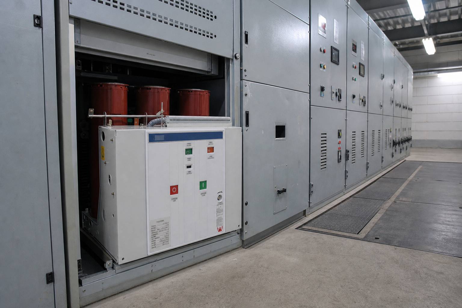
What Does a Switchgear Room Actually Have to Deliver?
A switchgear room is not a store for cabinets. It is a working environment that has to support five activities, and each one consumes space in a different way. Normal operation requires the operator to stand square to the panel, see the mimic and the indication, and reach the handle without stepping into a live compartment. Switching requires room for a racking handle and for the arc that a fault may produce at the moment of operation. Maintenance requires the rear or front of the cabinet to be opened, tested and worked on with instruments. Cable work requires a trench, a pulling radius and a person at the bottom of it. Emergency response requires a route out that does not pass in front of the fault.
Two of those activities are frequently underestimated. Racking a withdrawable breaker out of its cubicle needs more clear floor than operating it, because the breaker travels toward the operator and then has to be lifted or trolleyed away. And partial discharge testing, primary injection or a dielectric test needs instrument leads, a test set and a clear standing area that a room sized only for the closed cabinet does not have.
The practical conclusion is that the room should be sized from the equipment's operation and test envelope, not from its footprint. A cabinet 800 mm deep behaves like a 2,400 mm deep object once a person, a handle and a test lead are in front of it.
How Much Floor Space Does a Switchgear Room Need?
Three measurements decide the floor plan: cabinet depth, front working aisle and rear access. For metal-enclosed 12–40.5 kV equipment the cabinet body is typically 800–1,000 mm deep for a fixed unit and 1,500–1,700 mm for a withdrawable one, and the room has to add the aisles to that.
| Layout element | Range seen in 11 kV and 33 kV rooms | What drives the figure |
|---|---|---|
| Front operating aisle | 1,500–2,200 mm | Racking travel, door swing, operator stance, arc-fault egress |
| Rear maintenance aisle | 800–1,200 mm | Cable termination access, CT/VT replacement, test leads |
| Single-row room width | 3,000–4,500 mm clear | Cabinet depth plus front aisle plus rear aisle plus wall clearance |
| Double-row room width | 6,500–9,000 mm clear | Two cabinet depths plus a shared centre aisle |
| Clear height under beam | 3,000–4,000 mm | Busbar and cable riser bends, pressure relief duct, luminaire swing |
| Cable trench depth | 600–1,000 mm | Bend radius of the largest cable, joint space, drainage fall |
Where the switchgear faces a wall with no rear access — a common arrangement for a ring main unit — the aisle has to carry the whole maintenance load, and 1,500 mm stops being generous. Where both front and rear are accessible, the front aisle can stay at the lower end only if the breakers are fixed-type rather than withdrawable.
Height is the measurement most often lost. A 40.5 kV cabinet with a pressure-relief flap on top needs clear space above it, and if that space is a duct it has to be sized for the hot gas volume rather than for the flap. Cable risers entering from below need a bend radius that puts the first support above floor level, which in turn sets the minimum distance from the cabinet end to the wall.
What Clearances and Access Widths Apply?
Clearance is a safety requirement before it is an ergonomic one. The distances that matter are the ones a person occupies while equipment is live, and they differ from the distances that matter when it is dead and earthed.
- Doors and escape routes. A switchgear room needs two ways out where the floor area and the number of panels justify it, and at least one door that opens outward in the direction of escape. A clear width of 1,200 mm is a common minimum for a door serving equipment; corridors narrower than that become the bottleneck when a person has to leave quickly.
- Panel-to-panel gaps. Adjacent cabinets are bolted together, so the gap is zero — but the end cabinet still needs side clearance for a busbar extension, a cable riser or a future panel, and that clearance is much cheaper to build than to retrofit.
- Obstruction above and beside the aisle. A cable tray at 2,200 mm above a 1,800 mm aisle is not an obstruction; a fire pipe at 1,900 mm is. Services crossing the working aisle should be routed above the cabinet tops or in the floor.
- Floor loading and finish. A cabinet row is a line load, not a point load, but a battery room or a cast-resin transformer next door can be both. A sealed, dust-free floor with a defined fall away from the cabinets is the finish that survives cable pulling and trolley traffic.
One clearance is routinely missed because it appears on no drawing: the space needed to remove a VT or CT from a compartment. Where instrument transformers are mounted on a removable truck, the truck has to come out; where they are bolted to the partition, the panel in front of them has to open. Both need aisle depth, and neither is visible in a plan view of closed cabinets.
How Is Heat Removed Without Letting Humidity In?
Every watt dissipated inside a cabinet leaves it as heat, and the room has to remove the total of all the rows plus the solar and transmission gain through the walls. The calculation is simple — sum the losses at the design load, add the room gain, divide by the allowable temperature rise — but the inputs are usually guessed, and the result is a room that holds 45 °C in August while the equipment is rated at 40 °C.
Losses at 12 kV are modest per panel, in the region of a few hundred watts for a feeder cubicle, but they multiply across a row, and a busbar joint with rising resistance adds to the total quietly over years. The design should use the manufacturer's dissipated-power figure at rated current, not a generic watts-per-panel rule, and it should apply a margin for the load growth the room will inevitably see.
The second half of the problem is that the cheapest way to remove heat — open the room to outside air — imports humidity, dust and salt. In a coastal or Gulf climate that trade is almost always wrong. Three arrangements cover most projects:
| Arrangement | Works where | Watch out for |
|---|---|---|
| Natural ventilation through low inlet and high outlet | Dry, temperate sites with a modest total loss | Stack effect collapses when the outlet is smaller than the inlet; humidity enters unchecked |
| Forced ventilation with filtered inlet | Higher losses, dusty environment, moderate humidity | Filter loading raises room pressure and temperature; fan failure is silent |
| Closed room with split or ducted air conditioning | Humid, hot or polluted sites; rooms with electronics | Condensate must drain outside; cooling below the dew point of the room wets the cabinets |
Whichever is chosen, the room needs a thermometer that someone reads and a record that someone keeps. A switchgear room that has never been temperature-logged has no evidence that its ventilation was sized correctly, and the first hot week is a poor time to discover it. The same reasoning applies inside the cabinet, where anti-condensation heaters handle the surfaces the room cannot: the condensation guide covers the mechanism and the control.
How Should the Room Be Ventilated?
Ventilation has two jobs and they pull in opposite directions: remove heat, and keep moisture out. A louvre sized only for heat will, in a humid climate, be the path by which the room reaches 90 percent relative humidity overnight and condenses on every cold steel surface by morning.
Sizing starts from air changes rather than from instinct. Six to ten air changes per hour is the range that appears in room specifications for electrical spaces, but the number that matters is the outlet air temperature: if the leaving air is more than about 10–15 K above the inlet, the flow is too low for the loss. Inlet and outlet should be on opposite sides of the room and at opposite heights, with the inlet low and filtered and the outlet high and, ideally, above the hottest row.
Where the room is air-conditioned, the unit's evaporator becomes the coldest surface in the space. Mount it where its condensate cannot drip onto a cabinet, drain it outside the room rather than into the cable trench, and set the room temperature a few degrees above the outdoor dew point rather than as low as the unit can go.
One detail decides whether any of this survives contact with the site: the louvre must be insect- and bird-proofed without being blocked by a mesh so fine that it halves the free area. Free-area calculations are usually done on the gross opening and then quietly lost to a 2 mm mesh and a filter that is never changed.
How Is the Switchgear Room Earthed?
The earthing system in a switchgear room has to do three things at once: hold the cabinet frames and all extraneous metal at earth potential, provide the return path for fault current, and keep step and touch voltages at the working positions within tolerable limits for the duration the protection takes to clear.
In practice that means a ring or grid of earth conductor buried or cast into the floor slab, bonded to the building steel and to every cabinet frame at more than one point, with a dedicated earthing bar run along the room and tapped by each panel. The cross-section follows the fault current and its duration rather than the room size, and the joints are the part that fails: a bolted joint to a painted frame is not a bond, and a bond that relies on a star washer through powder coat will read correctly at commissioning and badly three years later.
Resistance targets vary by utility and by the purpose of the earth. Values between 1 and 4 ohms are commonly specified for an installation earth, with lower figures where the earth also serves a substation or a telecommunications installation; the number that matters is the one in the project specification, measured with a fall-of-potential test rather than inferred from a clamp reading. The bonding detail inside the cabinet — the earthing bar, the earth switch, the VT and CT secondary earthing — is covered in the earthing and bonding guide, because the room earth is only as good as the first connection to it.
What Do Fire, Flood and Cable Entry Requirements Change?
These three details are decided late, cost the most to change, and are the ones an insurer or a utility inspector will ask about first.
- Fire separation. A switchgear room is usually a fire compartment in its own right, with rated walls and a self-closing fire door, and the cable penetrations are where the rating is lost. Every entry needs a sealed, tested penetration system, not foam and sealant applied on the day of handover.
- Detection and extinction. Smoke detection in the room and, where the cabinets are unattended, detection inside the cable compartment. Water is the wrong agent above live equipment; clean agent or CO2 is the usual choice, with portable extinguishers at the door and a clear label of what is installed.
- Flood path. The cable trench is a drain whether or not one was designed. Give it a sump and a pump, or a fall to a drain outside the room, and raise the cabinet plinth above the predicted flood level. A room that fills to 200 mm puts water into every cable box on the row.
- Cable entry sealing. Each entry should be sealed around the cable and blocked as a group, so that the trench is not a chimney drawing humid air into the room and the room is not a chimney drawing it into the cabinet.
Lighting belongs in the same list because it is inspected with them: 200–300 lux at the panel front, emergency luminaires on a maintained circuit, and a socket outlet for test equipment at each end of the row. None of it is expensive before the walls are finished.
Which Checks Close Out the Room Design?
A room design is complete when each of the following can be answered with a number or a drawing reference rather than a description.
- Cabinet depth, front aisle and rear aisle stated, with the racking and test envelope drawn on the plan.
- Total dissipated power at rated load, the design ambient, and the resulting air flow or cooling capacity, with the manufacturer's figures attached.
- Ventilation route drawn from inlet to outlet, with free areas, filter class and the maintenance interval for the filter.
- Earthing arrangement, conductor size, bond points and the measured resistance target with the test method named.
- Fire rating of walls, door and penetrations, with the penetration system's certificate referenced.
- Trench depth, fall, sump and the flood level the plinth is raised above.
- Lighting level, emergency circuit and test sockets.
That list is short enough to attach to a drawing as a schedule. Most of the failures described in this article are not engineering errors; they are items that were never written down, and therefore never checked, on a room that was otherwise built exactly as drawn.
Where Nahu Group Fits
Nahu Group supplies the equipment that occupies the room — metal-enclosed switchgear, ring main units, vacuum circuit breakers, instrument transformers and metering boxes for 11 kV and 33 kV networks — and the room requirements follow from the equipment selection. Cabinet depth, the direction of the cable entry, the position of the pressure relief and the heat dissipated per panel are all fixed by the model chosen, which is why the room drawing and the equipment schedule should be approved together.
The useful input from a buyer is the single-line diagram, the fault level, the ambient and the available floor area. With those, the distribution cabinet range can be matched to the room rather than the room being rebuilt around a catalogue default, and the aisle dimensions can be confirmed against the actual racking travel of the breaker.
A switchgear room is cheap to size correctly at concept stage and expensive to correct after the walls are up. The four numbers that decide it — depth, aisle, heat and earth — can all be fixed before the equipment order is placed.
Frequently Asked Questions About Switchgear Room Design
How much floor space does a switchgear room need?
Allow for cabinet depth plus a front operating aisle of 1,500-2,200 mm and, where the rear is accessible, a maintenance aisle of 800-1,200 mm. A single row of 12 kV cabinets typically needs 3,000-4,500 mm of clear width and 3,000-4,000 mm of clear height. Size from the racking and test envelope, not from the closed cabinet footprint.
What is the minimum clearance in front of switchgear?
For withdrawable equipment the front aisle is set by the travel of the breaker truck plus the space a person needs to stand clear, which puts the practical range at 1,500-2,200 mm. Fixed-type panels can work at the lower end. The figure that matters is the racking envelope drawn on the layout, not a rule-of-thumb aisle width.
Does a switchgear room need mechanical ventilation?
It needs a defined heat-removal path, which may be natural, forced or refrigerated. Six to ten air changes per hour is a common starting range for electrical rooms, but the design check is the leaving-air temperature rise across the room. On humid sites, unfiltered ventilation imports the moisture that condenses on cold steel overnight.
Can a switchgear room be air conditioned?
Yes, and on hot or humid sites it is often the better choice, provided the condensate drains outside the room rather than into the cable trench and the room setpoint stays above the outdoor dew point. An over-cooled room wets every cabinet the moment a door is opened.
What earth resistance should a switchgear room achieve?
Values between 1 and 4 ohms are commonly specified for an installation earth, with lower figures where the earth also serves a substation. The governing number is the one in the project specification, and it should be proven by a fall-of-potential test rather than a clamp reading.
How deep should the cable trench be?
Typically 600-1,000 mm, set by the bend radius of the largest cable, the space needed for joints and the fall to a sump or drain. A trench that is also the room's only air path should be sealed at the entries so it does not act as a chimney.
Does a switchgear room need two exits?
Where the room is long, has more than one row of panels, or is remote from the building's normal circulation, two exits are the usual requirement, with at least one door opening outward in the direction of escape. A clear door width of 1,200 mm is a common minimum for equipment rooms.
Published November 2, 2026 · Nahu Group (NAHU Electric Technology)