
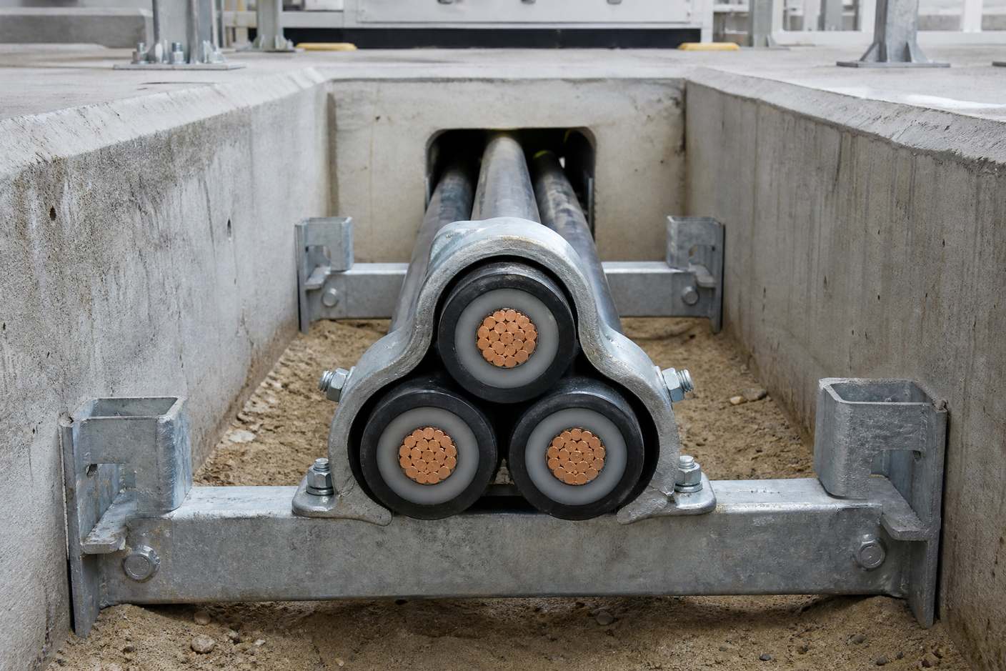
Trefoil formation is the arrangement of three single-core cables in a touching triangular group, one cable per phase, so that the magnetic fields of the three phases largely cancel instead of linking the metallic sheaths. It is the default formation for single-core power cables wherever the cable rating and the installation allow it, because it reduces induced sheath voltage, keeps the circuit compact and lets the three cables be restrained as one group against short-circuit forces.
The formation is only half the decision. What happens to the voltage that remains on the sheath — solid bonding at both ends, single-point bonding with a voltage limiter, or cross-bonding over three minor sections — determines whether the circuit keeps its full current rating or quietly loses part of it to circulating current.
This guide covers what trefoil formation does electrically, how it compares with flat formation, how the three bonding methods behave, and the installation details that decide whether the scheme survives its first ten years in the ground.
What Is Trefoil Formation and Why Does It Matter?
In trefoil formation the three cable centres form a triangle, with the cables touching or nearly touching, held by a cleat that clamps all three together. Each cable carries one phase. The arrangement appears on LV, MV and HV single-core circuits — 600/1000 V, 11 kV, 33 kV, 66 kV and above — wherever the design uses three separate cables instead of one three-core cable.
The reason is electromagnetic rather than mechanical. A single-core cable carrying alternating current produces a magnetic field that links its own metallic sheath. In a three-core cable the three phase currents sum to nearly zero, so the net field outside the cores is small and the induced sheath voltage is negligible. Single-core cables lose that cancellation: each conductor has its own sheath, and its field links that sheath fully.
Grouping the three phases closely restores most of the cancellation. The induced voltages in the three sheaths are 120 degrees apart, and when the cables are close together the vector sum is much smaller than the sum of the individual magnitudes. That is the whole electrical case for trefoil, and it is why the formation is specified before the bonding method rather than after it.
How Is Sheath Voltage Induced in a Single-Core Cable?
Two coupling mechanisms act at once, and they behave differently.
- Inductive coupling is the dominant effect under load. The alternating current in the conductor creates a changing magnetic field that links the sheath, inducing a voltage along its length. The magnitude rises with conductor current, with frequency, with the mutual inductance between conductor and sheath, and with the cable length.
- Capacitive coupling comes from the electric field between conductor and sheath, with the insulation acting as the dielectric. It produces a displacement current that matters most on lightly loaded or unloaded cables, where the inductive component is small but the charging current is not.
Written as a relationship, the induced sheath voltage for a length L is proportional to the mutual reactance between conductor and sheath and to the conductor current. The practical consequence is that standing voltage accumulates with route length: a circuit short enough for one bonding method becomes unsuitable for another purely because it got longer, with no change to the cable.
Circulating current behaves differently. It is driven by the net electromotive force round a closed loop and limited by the loop impedance. Both scale with length, so their ratio — and therefore the circulating current — stays roughly constant as the route grows. That asymmetry is the single most useful fact in sheath bonding: length punishes standing voltage, not circulating current.
Trefoil vs Flat Formation: Which Should You Specify?
Both formations are legitimate. The choice is a design decision driven by rating, fault level, route geometry and the bonding scheme, not a matter of installer preference.
| Trefoil formation | Flat formation | |
|---|---|---|
| Arrangement | Three cables in a touching triangular group | Three cables side by side in a row, spaced apart |
| Induced sheath voltage | Lower, because the three phases are magnetically close | Higher, and unequal between phases; the outer phases see more than the middle one |
| Route width | Compact footprint | Needs more width, which can matter in trenches and ducts |
| Heat dissipation | Grouped cables heat each other; check the rating for the actual grouping | Greater spacing can help thermal performance where the route allows it |
| Short-circuit restraint | Restrained as one group by a trefoil cleat | Restrained individually, or by a cleat designed for flat formation |
| Typical use | Substations, risers, ladders, trays, most MV single-core routes | Long buried routes and situations where spacing or access drives the layout |
The asymmetry in the flat case is worth repeating, because it is frequently missed in review: in a flat arrangement the two outer phases see a larger induced voltage than the middle one, so the three sheaths are not electrically equivalent even though they look it. Any bonding calculation that assumes symmetry is wrong for that layout.
What Are the Three Sheath Bonding Methods?
Bonding decides what happens to the induced voltage. Each method trades one problem for another, and the trade is explicit.
- Solid bonding earths the sheath at both ends. The sheath can never stand far above earth, which is good for anyone touching the cable, but the induced voltage drives a current round the loop formed by the sheath, the earth and the other sheaths. That current heats the sheath and takes current-carrying capacity away from the conductor. On a short run inside a substation the loss is small; on a long, heavily loaded circuit it can be large enough to force a bigger conductor size.
- Single-point bonding earths the sheath at one end only and leaves the far end insulated, normally through a sheath voltage limiter that behaves as an open circuit at normal voltage and conducts during a fault or surge. With no closed loop there is no circulating current, so the cable keeps its rating. The price is a standing voltage that rises linearly from the earthed end to the open end, which limits the practical route length, plus the need for a separate earth continuity conductor laid close to the cables so that fault current has a low-impedance return path.
- Cross bonding divides the route into three roughly equal minor sections and transposes the sheath connections at each joint, so that over one major section the three induced voltages add to approximately zero. The sheath is still earthed at the ends of each major section, circulating current is suppressed and standing voltage stays controlled. The cost sits in the accessories: link boxes, joints with sectionalised sheaths, and sheath voltage limiters at every transposition point.
Which Bonding Method Fits Which Route?
The comparison below is the one to bring to a design review, because it makes the consequence of each choice visible before the route is fixed.
| Circulating current | Standing voltage | Extra hardware | Where it fits | |
|---|---|---|---|---|
| Solid bonding | Present, rises with load and length | Held low along the route | None beyond the earth connections | Short runs, lightly loaded feeders, most three-core circuits |
| Single-point bonding | None, because there is no loop | Rises to a maximum at the insulated end | Sheath voltage limiter, earth continuity conductor | Routes short enough for the standing voltage to stay within the operator's limit |
| Cross bonding | Suppressed by cancellation | Controlled across each major section | Link boxes, sectionalised joints, limiters at transpositions | Long HV routes where neither of the simpler methods works |
Two design habits follow. First, settle the bonding method at specification stage, together with the formation, the armour material and the conductor size, because all four interact. Second, treat the bonding leads, link boxes and limiters as part of the circuit design rather than as site details — they belong on the drawings with the cable.
The accessory side of the same decision is covered in our guides to the cable joint kit and to cold-shrink versus heat-shrink terminations.
Why Do Single-Core Cables Need Non-Magnetic Armour?
The same field that induces sheath voltage also acts on any armour. Steel is magnetic, so a galvanised steel wire armour around a single-core AC cable carries eddy-current and hysteresis losses on top of the sheath circulating current. That is why single-core cables for AC service are normally armoured with a non-magnetic material such as aluminium wire, or supplied unarmoured and given mechanical protection by the installation.
This is a specification check rather than a manufacturing preference. A requirement for steel wire armour on a single-core AC cable is a mistake that is cheap to correct in the enquiry and expensive to correct once the cable is made. The armour choice follows the installation, and the installation follows the bonding scheme.
How Do You Restrain Cables in Trefoil Formation?
Under short-circuit conditions the electromagnetic forces between cables are large and act to move them. Trefoil cleats are not cable tidies; they hold the group to the support structure through the fault, and their selection is an engineering exercise.
Selection depends on the actual outside diameter of the three cables in formation, the prospective fault current, the cleat spacing, the strength and stiffness of the support structure, and the route geometry — bends and vertical runs usually need closer spacing. IEC 61914 is the standard for cable cleats and covers mechanical strength, short-circuit testing, impact, corrosion and environmental classification, so a cleat's test data is the basis for accepting it rather than its fit on the cable.
The common site failures are predictable: cable ties used where tested cleats are required, cleats chosen by diameter alone without reference to fault level, spacing set by eye, and support structures too light to take the restraint force. Each of these leaves a circuit that passes inspection and fails its duty.
What Goes Wrong on Site?
Most bonding problems are installation problems, and they share a characteristic: they are invisible until something else fails.
- Damaged oversheath. Single-point and cross bonding both depend on the outer sheath staying intact. A gouge or a badly made joint earths the metallic sheath at an unplanned point and quietly restores the circulating current the scheme was designed to avoid. Oversheath integrity testing after installation, and again after excavation near the route, is what keeps the design honest.
- Phases grouped wrongly. The three phases must stay in the correct order along the whole route. A transposition mistake in the trench undoes the cancellation the formation was chosen for.
- Limiters selected for normal operation. Sheath voltage limiters protect against transient overvoltages, and they should be selected for the fault condition rather than the steady-state voltage they see every day.
- Bonding left to the jointer. When the scheme is decided on site, the cable rating was calculated against a different arrangement. The remedy after energisation is a derated circuit or a re-laid one.
Does Trefoil Formation Apply at 11 kV and 33 kV?
Yes. Trefoil is common on 11 kV and 33 kV single-core circuits in substations, industrial plants and utility networks, and on 66 kV and higher transmission routes where single-core cable is used. What changes with voltage is not the principle but the consequence: at higher voltages the standing voltage on an insulated sheath reaches significant levels over shorter lengths, and the accessory set — joints, terminations, link boxes and limiters — becomes a larger share of the design effort.
Below 33 kV many designs avoid the question entirely by using three-core cable, whose common screen makes the sheath problem negligible. Where single-core cable is chosen anyway — large LV feeders, generator connections, transformer tails, tight routes — the formation and bonding decisions come back into scope.
How Do Terminations and Joints Fit the Scheme?
The cable accessory is where the bonding scheme becomes physical. A single-core termination has to shed the sheath or screen in a controlled way, bring the metallic screen out to a bonding lead, and maintain the insulation distance that the cable design assumes. A joint in a cross-bonded route is not a standard joint: it must sectionalise the sheath so the transposition can be made, and it must be identifiable as such on the drawings.
Nahu Group manufactures cold-shrink cable accessories for 10–35 kV networks, including single-core indoor and outdoor terminations and straight joints, alongside cable branch boxes and separable connectors. Because the accessory set follows the bonding decision, the useful enquiry is the complete one: system voltage, conductor size, formation, bonding method, fault level and the environment the joint will sit in.
Where a branch is taken off the route, the enclosure that receives it has its own requirements, covered in the guide to European-style cable branch boxes.
Frequently Asked Questions
What is trefoil formation in cable installation?
Trefoil formation is the arrangement of three single-core cables in a touching triangular group, one cable per phase, held by a cleat that clamps all three. It keeps the phases magnetically close, which reduces the voltage induced in the cable sheaths and produces a compact, easily restrained route.
Why is trefoil better than flat formation?
Trefoil reduces induced sheath voltage because the three phases are close together and their induced voltages partially cancel. In a flat arrangement the cables are spaced apart, induced voltage is higher and the two outer phases see more than the middle one. Trefoil is also more compact and easier to restrain as a group.
Does trefoil formation remove sheath voltage completely?
No. It reduces the induced voltage but does not eliminate it. A residual voltage remains, and what happens to it depends on the bonding method: solid bonding holds the sheath near earth potential at the cost of circulating current, while single-point and cross bonding control circulating current but leave a standing voltage that has to be managed.
What is the difference between solid bonding and single-point bonding?
Solid bonding earths the sheath at both ends, which keeps sheath voltage low but allows circulating current that heats the sheath and reduces the cable rating. Single-point bonding earths one end only, which removes the circulating loop but leaves a standing voltage rising along the route and requires an earth continuity conductor.
Why does standing sheath voltage increase with cable length but circulating current does not?
Standing voltage is the accumulation of induced electromotive force along the route, so it grows with length. Circulating current is driven by the net loop voltage and limited by the loop impedance, and both of those scale with length, so their ratio stays roughly constant.
Why can't single-core AC cables use steel wire armour?
Steel is magnetic, so a steel wire armour around a single-core AC cable carries eddy-current and hysteresis losses in addition to sheath circulating current. Single-core cables for AC service are therefore normally armoured with a non-magnetic material such as aluminium wire, or supplied unarmoured with mechanical protection provided by the installation.
Which standard covers trefoil cable cleats?
IEC 61914 is the international standard for cable cleats. It covers mechanical strength, short-circuit testing, impact, corrosion and environmental classification, and it is the basis for accepting a cleat for the restraint duty it will face rather than for whether it physically fits the cable.
Do three-core cables have the same sheath problem?
No, and that is why three-core cable is the default on many MV feeders. The three phase conductors share a common screen, the currents sum to nearly zero, and the net magnetic field outside the cores is small, so the induced sheath voltage is negligible and the sheath can be earthed at both ends.
Sources and Further Reading
- ELEK — Cable sheath induced voltage calculations — inductive and capacitive coupling, bonding arrangements, length dependence
- APAR — Sheath bonding for single-core cables — circulating current losses, the three bonding methods, armour material
- Thorne & Derrick — Trefoil cable formation explained — formation geometry, cleating and restraint, IEC 61914
The sequence that avoids rework is short: choose three-core cable if the conductor size allows it, choose trefoil and solid bonding where single-core cable is required and the run is short, and move to single-point or cross bonding only when the calculated standing voltage or sheath loss says you must. Decide it on the drawing, with the accessory set, and the installation has a chance of matching the calculation.
For 10–35 kV cable accessories — cold-shrink terminations, straight joints, separable connectors and branch boxes — Nahu Group can confirm the accessory set that matches a given formation and bonding scheme. See the cable accessories range or send the cable schedule to the engineering team.
Published October 18, 2026 · Nahu Group (NAHU Electric Technology)