
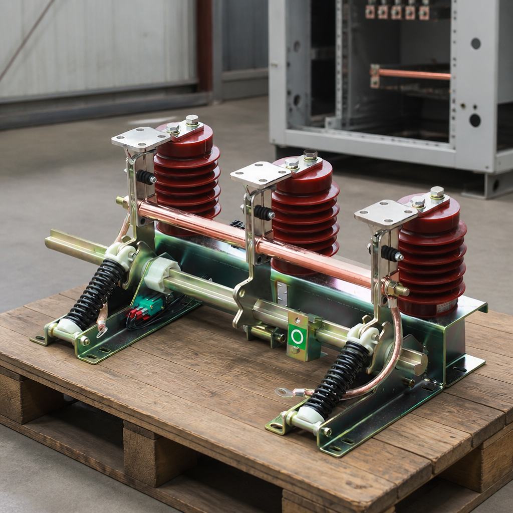
An earthing switch is a mechanical switching device that connects a circuit to earth so that work can be carried out on it safely. It is not a load-breaking device: it does not have to make or break load current, and it must never be used to open a live circuit. Its job is to be closed onto a de-energised and isolated section — and, on fault-making designs, to be capable of closing onto a circuit that is still live, so that a switching mistake does not become an arc flash. Once closed, it also carries the rated short-circuit current of the system, which keeps the section safe if it is re-energised at the remote end.
The short form of the name is the earth switch, and in some markets the same device is called a grounding switch. Whatever it is called, that combination of duties — a device that cannot break load current but may have to close onto a fault — is what makes it a specification subject rather than an accessory. This guide covers how an earth switch differs from a disconnector and a load break switch, what the ratings mean, why interlocking is the whole point, and where these devices sit inside an RMU or a cabinet.
What Is an Earthing Switch?
The engineering reference description is unusually blunt: an earth switch "is not a switch as described in Section 34.1.2 because it does not have to make or break load current". Its function during a safe isolation is to connect the isolated section to the earthing system, after the section has been disconnected and proved dead.
Once it is closed, the earth switch has a second duty that is easy to overlook. In the closed position it must be capable of carrying the rated short-circuit current of the system for the rated time — a requirement that exists "to safeguard against the circuit being inadvertently re-energised at its remote end". In other words, the earth switch is also the last line of defence against a circuit being energised from the other end of the network while someone is working on it.
A third duty is optional but increasingly expected. Some authorities insist that line-end and cable-end earth switches must additionally be capable of safely closing onto an energised circuit. Units built to that requirement are referred to as fault-making earth switches, and power-operated mechanisms are an essential part of them.
How Does an Earth Switch Differ from a Disconnector and a Load Break Switch?
Three devices, three different capabilities, and one rule that keeps operators safe: only one of them is allowed to interrupt current.
| Earth switch | Disconnector (isolator) | Load break switch | |
|---|---|---|---|
| Main purpose | Connect a section to earth for safe working | Provide a visible isolating distance | Switch load current on and off |
| Can it break load current? | No — it does not have to make or break load current | No — it is not intended to interrupt circuit currents | Yes — it is capable of closing against and interrupting circuit load currents |
| Can it close onto a fault? | Only the fault-making versions, which are rated for it | Not as a fault-making duty | Rated for its specified making capacity |
| Speed of operation | Set by the mechanism and the making duty | Generally slow in operation, because current interruption is not its job | Fast, because it has to quench or transfer an arc |
| Interlocked with | The associated disconnector or the circuit breaker, so an earth can only be applied to an isolated section | The earth switch and the circuit breaker | The earth switch in the same circuit |
The table explains a rule that appears in every switching procedure. An earth switch is operated after isolation, never instead of it. If a section has to be isolated for maintenance, the sequence is: break the load with a device rated to break it, establish the isolating distance with a disconnector, prove the section dead, then close the earth switch. Reversing any pair of those steps is how people are injured.
What Do the Ratings Actually Mean?
Two ratings are confused constantly, and the confusion is expensive because they answer different questions.
| What it answers | Why it matters | |
|---|---|---|
| Rated short-time withstand current, with its duration | How much current the closed device can carry for a defined time | Keeps the section safe while it is earthed, if it is energised from the remote end |
| Rated peak withstand current | The peak value the equipment withstands during the transient | A separate quantity from the short-time current; both appear on a real rating table |
| Rated short-circuit making current | The current the device can be closed onto | This is what makes an earth switch fault-making or not |
| Classification for short-circuit making capability | How many fault-making operations the switch is classified for | It distinguishes a unit that can never close onto a fault from one that is expected to |
A type-tested manufacturer's data sheet shows the two withstand quantities sitting in different rows of the same table — a rated peak withstand current stated separately from a rated short-time withstand current given for a defined duration, alongside a rated short-circuit making current. The distinction is not academic: the peak value describes the first major loop of a transient, while the short-time value describes what the equipment can carry for a stated time.
The endurance classification is written as a small set of classes, and it is the fastest way to tell a device that is merely a safety link from one that is expected to close onto a live fault:
- E0 — no fault-making capability
- E1 — classified for two fault-making operations
- E2 — classified for five fault-making operations
A distribution network operator's switchgear standard states the preference plainly: to reduce the impact of switching errors, earth switches should be rated for fault make (E1 or higher) where practical. If a specification leaves the class blank, the offer may legitimately be E0 — which is compliant, and unusable in a bay where the circuit cannot be proved de-energised.
Why Is Interlocking the Whole Point?
Everything about these devices assumes they are operated in the right order. The device itself cannot enforce that, so the enclosure does. Earth switches are normally interlocked, mechanically or electrically, with the associated disconnector, in such a way that an earth can only be applied to a part of the system that has already been de-energised and isolated.
The standard has moved in the same direction. The current edition of the disconnector and earth-switch standard added new withstand requirements for interlocking devices and a new subclause for testing mechanical interlocking devices, alongside a new class of mechanical endurance for earth switches. Interlocking is treated as a rated, testable function, not as an accessory bracket.
Two interlocking arrangements are common, and they are worth naming in an RFQ because they change what the operator can do and what the panel has to look like:
- Interlock with the disconnector or circuit breaker. The earth switch cannot be closed unless the associated switching device is open and the section is isolated.
- Interlock that also prevents the reverse. The switching device cannot be closed while the earth is applied. A one-way interlock that stops an earth being applied to a live section, but allows the section to be energised with the earth still closed, is a design defect rather than a compromise. On a three-position disconnector the same logic is built into the mechanism: it can only be operated with the circuit breaker in the open position.
Where Do They Sit in an RMU or a Cabinet?
In metal-enclosed switchgear, the earth switch is a fixed part of the bay rather than an add-on. A typical gas-insulated bay carries three of them — one on the bus side of the circuit breaker, one on the line side of the circuit breaker, and one on the line itself — and it is the line earth switch that has to be fault-making, precisely because the line circuit has only a limited ability to be tested and proved de-energised.
Ring main units use the same principle on the cable side. Fault-making earth switches, and cable test facilities, may be built into the cable side of each ring switch so that a cable can be safely earthed, repaired if necessary, and re-tested. That arrangement is the reason a ring network can be worked on one leg at a time at all — the cable is earthed at the switch, the fault is located and cleared, and the cable goes back into service without the rest of the network being disturbed.
In a cabinet, three construction patterns are common. The earthing function may be provided by a separate device mounted in the cable compartment; it may be combined into a three-position disconnector that serves as busbar disconnector and feeder earth switch; or it may be obtained through a make-proof device — for example make-proof earthing by means of the vacuum circuit breaker itself, in a panel designed that way. Which pattern is used changes the interlocks, the operating sequence and the maintenance access, so it belongs in the single-line diagram discussion rather than in the procurement office. In Nahu Group's own switching range the earthing switch is supplied as a separate three-pole device for the bay, rather than being combined into a three-position disconnector.
How Do You Specify One for a Project?
A specification that states all of the following can be quoted and type-tested against without a clarification round:
- Rated voltage, rated frequency, and whether the unit is for indoor or outdoor installation
- Rated short-time withstand current and its duration, and the rated peak withstand current
- Whether fault-making capability is required, and if so the endurance class (E1 or E2) — state it explicitly rather than assuming it
- Number of poles, and the mounting arrangement in the cable compartment
- Operating mechanism: manual or power-operated, and the reason for the choice (a fault-making duty generally requires a power-operated mechanism)
- Position indication, and how the operator confirms the earth is applied
- The interlocking scheme, including the reverse interlock that prevents energising an earthed section, and whether mechanical or electrical
- Insulation level, creepage distance and the service conditions the bay will see
- The standard and edition the switch is type-tested to, the class within it, and the type-test report for the offered model
Where a cable-side unit is also used for cable testing, add that duty to the specification. A device specified only for earthing may not be the same product as one specified to leave the cable isolated and testable afterwards, and the difference shows up when the first fault has to be located.
Commissioning and Maintenance Checks
- Prove the interlock, in both directions. Attempt to close the earth with the section energised, and attempt to energise the section with the earth closed. Both must be prevented by the interlock, not by procedure alone.
- Check the contact alignment and the closed position. A three-pole unit that closes one pole ahead of the others is not making a three-phase earth.
- Verify the mechanism and, where fitted, the power operation. A fault-making device depends on the mechanism delivering its rated making current; a sluggish mechanism is a safety issue.
- Record the type-test reference, the endurance class and the date. The next engineer to plan work on that switch needs to know whether it can be closed onto a live cable.
Three Specification Mistakes That Recur
- Leaving the fault-making class unstated. The cheapest compliant offer is then the one that can never be closed onto a fault — and on a line or cable circuit, that is the case the device exists for.
- Specifying a one-way interlock. Preventing an earth being applied to a live section is only half the requirement; the reverse interlock is what protects the person working downstream.
- Treating the device as a detail of the enclosure. Its ratings, its mechanism and its interlocking scheme are the reason the bay can be worked on safely, and they need to appear on the drawing that the operator uses.
Frequently Asked Questions About Earthing and Grounding Switches
What is an earth switch used for?
It connects a circuit to earth so that work can be carried out on it safely. It is closed onto a section that has already been disconnected and proved dead, and it is never used to open or close a live circuit.
Can an earth switch break load current?
No. It does not have to make or break load current, and it must not be used for that purpose. Load has to be broken by a device rated to break it, such as a load break switch or a circuit breaker, before the disconnector and then the earth switch are operated.
What is a fault-making earth switch?
It is a unit classified and rated to close onto a circuit that is still energised, so that a switching error does not turn into an arc flash. Fault-making designs are generally power-operated, and they are classified for a defined number of fault-making operations — class E1 for two operations, class E2 for five.
What is the difference between short-time withstand current and short-circuit making current?
The short-time withstand current is what the closed device can carry for a stated duration; it is what protects the section if it is re-energised from the remote end. The short-circuit making current is what the device can be closed onto. One describes carrying, the other describes closing.
How many earth switches does a switchgear bay need?
A typical gas-insulated bay has three: one on the bus side of the circuit breaker, one on the line side of the circuit breaker, and one on the line itself. The line-side unit normally has to be fault-making, because a line circuit can rarely be proved de-energised with the same confidence as a busbar.
Why does an earth switch need an interlock?
Because its safety depends on the order in which it is operated. It is interlocked with the associated disconnector or circuit breaker so that an earth can only be applied to a section that is already de-energised and isolated, and the reverse interlock prevents the section being energised while the earth is still applied.
Are earth switches used in ring main units?
Yes. Fault-making earth switches, and cable test facilities, may be built into the cable side of each ring switch, so that a cable can be earthed, repaired if necessary and re-tested without disturbing the rest of the network.
What should a specification state?
Rated voltage and frequency, indoor or outdoor service; short-time withstand current and its duration; peak withstand current; whether fault-making capability is required and to which endurance class; the number of poles and the mounting arrangement; manual or power operation; position indication; the interlocking scheme including the reverse interlock; and the standard, edition and type-test report the unit is qualified against.
Sources and Further Reading
- IEC 62271-102 — High-voltage switchgear and controlgear, Part 102: Alternating current disconnectors and earthing switches — scope, the endurance classification for short-circuit making capability, and the new requirements for interlocking devices
- IEC 62271-102 first edition (2001), preview — records that the 2001 edition cancelled and replaced IEC 60129, the earlier standard that it superseded
- Distribution network operator standard for switchgear selection (Energy Queensland / Ergon Energy Network) — the E0/E1/E2 endurance classes, the fault-make preference, and the three earth switches in a typical GIS bay
- Medium-voltage gas-insulated switchgear catalogue (Siemens) — a type-tested rating table separating peak withstand, short-circuit making and short-time withstand current, and the three-position disconnector arrangement
- Switchgear chapter, Electrical Engineer's Reference Book — why disconnectors and earth switches are not load-breaking, the short-circuit withstand requirement, fault-making devices, interlocking, and earth switches in ring main units
An earth switch is the least expensive device in the bay and the one that stands between a switching error and an injury. Specify the making capability rather than leaving it to the offer, insist on an interlock that works in both directions, and make sure the operator can see that the earth is applied. Everything else about the bay can be re-engineered later; a device that is not fault-making cannot be.
Nahu Group (NAHU Electric Technology) manufactures the JN15-12/31.5 indoor high-voltage grounding switch — a 12 kV three-pole earthing switch for indoor 3–12 kV, 50/60 Hz systems, with a rated short-time withstand current of 31.5 kA — alongside its isolating switches, load break switches, ring main units, vacuum circuit breakers and metering equipment. See the earthing switch range, read how isolating switches are selected, or see where these devices appear on a drawing in the ring main unit single line diagram guide.
Published September 29, 2026 · Nahu Group (NAHU Electric Technology)