
Current transformer secondary earthing is the single connection that ties a CT secondary circuit to the station earth, and there must be exactly one of them per circuit. Earth the circuit in two places and fault current can circulate through the earth path, the panel metalwork and the neutral conductor, distorting measurements and stressing insulation. Earth it nowhere and the secondary floats at whatever potential a primary fault imposes. Commissioning engineers spend more time checking this one connection than almost any other in the protection scheme, because a missing or duplicate earth is invisible until something misoperates.
This guide covers where the earth point belongs, why the rule is one point rather than one point per core, how a three-phase set is connected, what happens when a secondary is left open, and the checks that catch the error before energisation. It is written for protection and commissioning engineers specifying 10–35 kV current transformers, and for the buyers who have to review the drawings they are handed.
One framing note before the detail: earthing practice is a system question, not a product feature. A CT does not arrive with an earth; the installer creates it. That is exactly why it goes wrong.
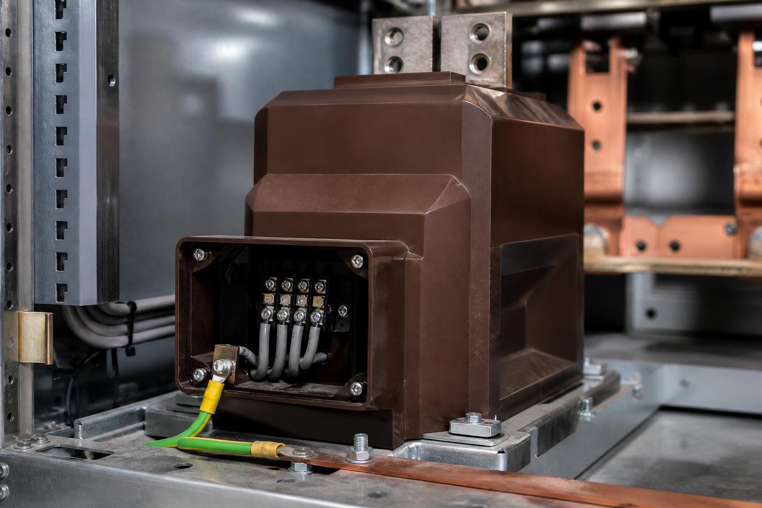
What Does CT Secondary Earthing Actually Connect?
A CT secondary circuit is not just the transformer winding. It is the winding, the terminal block at the transformer, the multicore cable, the test links, the relay current inputs, the meters and every device wired into that loop. All of it sits at one electrical potential, and the earth connection is what defines that potential relative to the station.
Secondary terminals are marked so that the winding can be identified unambiguously. In the IEC convention used across Europe and the Middle East, the primary terminals are P1 and P2 and the secondary terminals are 1S1 and 1S2, with the polarity terminal first. Manufacturers mark the terminals this way for a reason: the earth must be applied to a known end of a known winding, not to whichever terminal is nearest the cable gland.
The circuit therefore has three properties that have to be decided together: which core is being used, which terminal of that core is earthed, and where along the run the earth is made. Getting the first two right and the third wrong is the most common failure mode in the field.
Why Must a CT Secondary Circuit Be Earthed at Only One Point?
The earthing requirement is a safety requirement first and a measurement requirement second. If the insulation between the primary and secondary of a CT fails, or if a primary conductor touches the secondary circuit, the entire secondary loop rises to the primary potential. Without an earth connection there is no low-impedance path to clear that condition, and anyone touching a relay case, a meter or a terminal block becomes part of the fault path.
One earth solves that. A second earth creates a new problem. As Schweitzer Engineering Laboratories puts it in its review of CT and VT connection errors, the secondary circuit should be solidly grounded to the grounding grid at only one point, because multiple grounds may produce circulating currents that flow through the equipment connected between those grounds, causing inaccuracies in measurement and damaging the insulation of secondary wiring and neutral conductors.
That sentence deserves to be read slowly. The damage is not theoretical: the circulating current is driven by potential differences between two points on the station earth grid, and it flows through whatever sits between them — typically the neutral conductor and the current inputs of a relay. The loop exists whenever a fault raises the potential of one earth point relative to the other, which is precisely when the protection has to work correctly.
Where Should the Single Earth Point Be?
CT secondary earthing has two accepted locations: at the instrument transformer itself, or at the first point of application near the relay and switchboard terminals. Which one applies depends on whether the winding is in use.
For a core that is in service, the recommended location is the first point of application — the switchboard or control house where the relay sits. The reason is a fault-voltage argument. If the circuit is earthed at the transformer, then during an earth fault on the primary system the switchboard end of the cable can sit at a significant potential relative to local earth, which is hazardous to anyone working on the secondary device and may damage it. Earthing at the relay end keeps the equipment the engineer touches at earth potential.
There is a practical reason too: the earth has to be reachable so it can be lifted for testing. That is why the earth connection should be a bolted link or a dedicated stud, not a fuse, a contact, an auxiliary relay or any switching device that might open unexpectedly and leave the circuit unearthed without anyone noticing.
For a core that is not in service — a spare winding brought back to the panel but not connected to any device — earthing at the transformer location is the accepted practice. There is no secondary circuit to protect, so the hazard argument does not apply, and earthing locally keeps a floating winding from sitting at an undefined potential.
| Where the earth belongs | Why that location | What to avoid | |
|---|---|---|---|
| Core in service, wired to a relay or meter | At the first point of application: switchboard or relay panel terminals | Keeps the equipment an engineer touches at earth potential during a primary earth fault, and keeps the earth accessible for testing | Earthing at the CT terminal box as well, or earthing through a removable fuse or link that can be left open |
| Spare core, not connected to any device | At the CT location | No secondary circuit exists to protect; the winding still needs a defined potential | Bringing the spare core back to the panel unearthed, or earthing it at both ends |
| Three-phase set connected in star | At the star point, one earth only | The star point is the single electrical node common to all three cores | Earthing each phase core separately at the panel |
| Core used for residual or neutral current | At the first point of application, on the same principle as any in-service core | The residual circuit is a single circuit and takes a single earth | Treating the residual connection as a second, separately earthed circuit |
What Happens When a CT Secondary Is Earthed at Two Points?
Nothing, until the station earth grid carries current. Then the two earth points stop being at the same potential, and the secondary circuit becomes a parallel path for a fraction of that current.
Three consequences follow, in order of how quickly they are noticed:
- Measurement drift. The circulating current adds to or subtracts from the secondary current the relay expects. Revenue metering reads wrong, and the error is not constant — it appears under load and disappears when the station is quiet, which is why it survives so many investigations.
- Protection misoperation. A differential or residual scheme compares currents that are supposed to sum to zero. Circulating current breaks that assumption, and the relay sees a fault that is not there.
- Insulation damage. The neutral conductor and secondary wiring carry current they were never sized for, and the damage accumulates out of sight inside trunking and terminal chambers.
A second earth on a CT circuit is one of the recurring wiring errors catalogued in the SEL paper, alongside swapped phases, a cut cable insulation, a wrong tapping and a missing neutral. It is also the hardest to see, because both earths look correct when inspected separately. The error only exists as a relationship between two points several metres apart.
How Do You Earth a Three-Phase CT Set?
When three phase cores are connected in star, the three returns are joined at a single star point, and that star point is earthed once. CT secondary earthing has not changed here; the star point is simply the one node that is common to all three cores, so it is the natural place to define the potential of the whole set.
The mistake to watch for is treating each core as an independent circuit and giving each one its own earth at the panel. Electrically, that produces three earths on one interconnected circuit — the same defect as a double earth on a single core, multiplied. If the cores are genuinely separate circuits with separate relays, each circuit takes its own single earth, and the neutral points must not be tied together.
For a residual connection formed from three phase cores, the residual return is part of the same circuit and must not acquire a second earth of its own. Where a dedicated core-balance or neutral CT is used instead, it is a separate circuit and follows the ordinary single-earth rule.
What Happens If a CT Secondary Is Left Open?
An open secondary is the other half of the earthing discipline, and it is more dangerous than a duplicate earth. With the secondary open, the current that the primary would normally induce has nowhere to go, the core saturates, and dangerous voltage appears across the open terminals.
ABB states the rule plainly in its installation instructions for cable current transformers: if there is no burden connected to the secondary terminals, the secondary terminals must not be left open-circuited when the primary conductor is connected. The same logic applies whenever a burden is removed for testing — short the secondary first, then break the circuit, and remove the short last.
The consequence is not limited to the transformer. SEL lists an open-circuit CT among the common wiring defects that can cause personnel injury and equipment damage, and it sits in the same family of errors as a missing neutral: both leave a circuit that looks wired but cannot carry its current.
How Do You Verify CT Earthing at Commissioning?
Verification of CT secondary earthing is a sequence, not a single test. Each step rules out one way the circuit can be wrong.
- Visual check of the earth path. Confirm the earth conductor is continuous from the intended point to the earth bar, that it is not a fuse or a link, and that no second connection to earth exists at the transformer end, in a junction box or inside a marshalling panel.
- Continuity and isolation. With the circuit isolated, prove the earth is a solid connection, then prove there is no parallel path to earth from the same circuit. A continuity test that beeps at both ends of a run tells you nothing about how many earths exist.
- Inject and compare. Inject a known current through the primary, as in a primary injection test, and compare the relay reading against the injected value and against the other phases. An unexpected division of current between phases points to an unintended earth path.
- Check the neutral and the polarity together. Earthing cannot be verified in isolation from polarity and phase rotation, because all three determine whether the relay sees the quantity it was set for.
Record the earth point location on the commissioning sheet. The next engineer to work on the circuit needs to know where it is before they lift it.
Which CT Earthing Mistakes Recur Most Often?
Five errors account for most of the CT secondary earthing failures seen on 10–35 kV installations:
- Earthing at both ends of a multicore. The installer earths the screen and the spare core at the transformer, and the panel builder earths the neutral at the relay. Both are locally correct, and together they are wrong.
- Earthing an unused core at the panel. The opposite error, and equally common when a spare core is brought back "just in case".
- Using the cable armour or screen as the earth conductor. The protective earth of the secondary circuit is a dedicated conductor, not a by-product of cable construction.
- Undersized earth conductor. SEL notes that the grounding conductor should be at least as large as the phase conductors, citing IEEE C57.13.3-2014 for the requirement and the National Electric Safety Code practice of a #12 AWG copper minimum on grounds of mechanical strength and current-carrying capacity.
- A removable link left open. The earth was lifted for a test and never restored, or restored without being recorded. This is why the earth point should be identifiable and the restoration should be a signed step on the test sheet.
What Should a CT Specification or RFQ State About Earthing?
The transformer supplier controls the terminal arrangement, the marking and the terminal box; the installer controls the earth connection. A specification that separates those responsibilities prevents the argument later, and it is the only place where CT secondary earthing can be made contractual rather than assumed.
- Terminal designations and polarity marking on every core, so the earth can be applied to a known terminal.
- The number of cores, the ratio and the accuracy class of each, including spare cores — the earthing rule depends on which cores are in service.
- Terminal box arrangement and whether a separate earth stud is provided, with its size.
- The standard the transformer is designed and tested to, so test reports and routine test data can be checked against a named reference rather than a description.
Nahu Group manufactures current transformers, voltage transformers and metering units for 10–35 kV distribution networks, and supplies them with the terminal marking and test documentation that protection engineers need to verify an installation. The current transformer range covers bushing, wound-primary, split-core and three-phase combined designs.
Frequently Asked Questions About CT Secondary Earthing
Why is a CT secondary earthed at only one point?
One earth fixes the potential of the secondary circuit for safety without creating a path for current to circulate. Two earths connect two points of the station earth grid through the secondary circuit, and any potential difference between them drives current through the relay inputs and the neutral conductor.
Should the CT be earthed at the transformer or at the relay panel?
For a core in service, earth at the first point of application near the relay and switchboard terminals. That keeps the equipment an engineer touches at earth potential during a primary earth fault and leaves the earth accessible for testing. For a spare core that is not connected to any device, earth at the transformer.
Can a CT secondary be earthed at both ends?
No. Earthing at both ends creates the double-earth condition that causes circulating currents, measurement inaccuracy and insulation damage, and it can make differential and residual protection misoperate.
How is a three-phase CT set earthed?
The three cores are connected in star, and the star point is earthed once. Each core should not be given its own separate earth at the panel, because that produces multiple earths on one interconnected circuit.
What happens if the CT secondary is left open?
The core saturates and dangerous voltage appears across the open terminals, with risk of injury and equipment damage. Short the secondary before removing a burden, and remove the short only after the burden is restored.
Can the earth connection include a fuse or a test link?
A removable link is common so the earth can be lifted for testing, but it must be a bolted or clearly identified link that is restored and recorded. Fuses, contacts and auxiliary relays in the earth path are not recommended, because any of them can leave the circuit unearthed without warning.
How large should the CT earth conductor be?
At least as large as the phase conductors of the secondary circuit. SEL cites IEEE C57.13.3-2014 for that requirement and notes the NESC practice of a #12 AWG copper minimum, based on mechanical strength and current-carrying capacity.
Does a spare CT core need to be earthed?
Yes, but at the transformer rather than at the panel. A spare winding still needs a defined potential; what it must not have is a connection to a second earth at the far end of the run.
Sources and Further Reading
- Schweitzer Engineering Laboratories — The Missing Link: How CT and VT Connection Errors Affect Protection (technical paper, 2022) — the single-earth rule, circulating currents from multiple grounds, earthing location for used and unused windings, ground conductor sizing, and the catalogue of common wiring errors
- IEC 61869-2:2012 — Instrument transformers, Part 2: Additional requirements for current transformers — the product standard the transformer itself is designed and tested against
- ABB — KOLMA cable current transformers: instruction for installation, use and maintenance — terminal marking and the instruction not to leave the secondary open-circuited while the primary conductor is connected
Earthing is the cheapest part of a CT installation and the most expensive one to get wrong. It takes a few minutes at the panel to prove, and it can take a week of investigation to explain a metering error that traces back to a second earth nobody drew. For the product side of the same subject, see current transformer basics, the medium-voltage CT specification checklist, and the instrument transformer site testing checklist.
Published October 17, 2026 · Nahu Group (NAHU Electric Technology)