
The instrument security factor (ISF) of a current transformer is the multiple of its rated primary current at which the core saturates — and it exists to protect the instrument connected to the secondary. A metering CT is deliberately built so that its accuracy band ends at a defined point. Beyond that point the core saturates, the secondary current stops rising proportionally, and the meter downstream is spared the full fault current. A low factor means earlier saturation and more protection; a high factor means the CT keeps transforming further into the fault.
This is the one rating on a metering CT that buyers most often leave blank, and the omission has consequences in both directions. Specify it too low and the CT saturates during heavy but legitimate loading, so billing data disappears exactly when consumption is highest. Specify it too high, or not at all, and the meter is exposed to the full secondary current of a primary fault.
This guide explains what the factor describes, how it differs from the accuracy class that sits beside it on the same nameplate, why the connected burden changes what the number means in practice, and the clauses that make it verifiable rather than assumed.
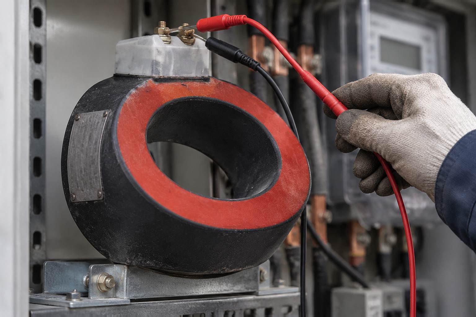
What Is an Instrument Security Factor?
A current transformer works by driving a magnetic core around its saturation region only at the top of its range. Below saturation the secondary current tracks the primary current closely enough for the ratio error and phase displacement to stay inside the accuracy class. At saturation the relationship collapses: the core can no longer support the flux the primary current demands, and the secondary current stops following.
The instrument security factor describes where that transition is placed, as a ratio rather than an absolute current. One manufacturer's low-voltage catalogue states it plainly: the factor is the ratio between the primary current that causes the core to saturate and the rated primary current, and — the part that matters for selection — the lower the factor, the higher the protection level on the transformer. Because it is a ratio, the factor travels with the ratio: the same factor on a 100/5 and a 600/5 unit describes very different absolute currents.
Two vocabulary traps are worth clearing up before going further. First, the symbol is not standardised across catalogues: ABB's low-voltage range marks it Sf, other manufacturers print FS, and both appear in project documents. Read the plate against the manufacturer's own legend rather than assuming the letters mean the same thing on every unit. Second, the factor is sometimes loosely called the "safety factor"; it is security of the instrument, not a safety margin on the CT's thermal rating.
Why Would a Metering Core Be Designed to Saturate?
It looks like a design defect until you follow the fault current. A metering CT is sized for the load, not for the fault level. On a feeder rated 400 A with a 20 kA fault level, the CT ratio might be 500/5, which means a close-in fault would ask the CT for a secondary current of two hundred amps. No revenue meter, no power quality analyser and no terminal block in a metering cabinet is built for that.
Saturation is the mechanism that prevents it. The core is chosen so that its accuracy range ends at a defined multiple of rated current, and beyond that the secondary output is clamped by physics rather than by a fuse. The measuring circuit sees a bounded current instead of a proportional one. That is the entire purpose of the rating, and it is why metering cores and protection cores are deliberately built to opposite objectives.
The protection core needs the opposite behaviour. It must transform accurately through the fault so that the relay sees the real current and can decide where the fault is. A protection core that saturated early would blind the relay at exactly the moment it is needed. The two requirements cannot be met by one core, which is why multi-core CTs exist and why the cores must be wired to the right circuits.
What Does the Number on the Nameplate Mean in Practice?
The factor is a multiple, so it converts into an absolute current with one multiplication and one reference to the ratio. A CT rated 200/5 with a factor of five is intended to hold its accuracy up to about 1,000 A primary and to saturate beyond it; the same factor on a 600/5 unit points at roughly 3,000 A.
Whether that is the right choice depends on the relationship between three currents at the site:
- The maximum legitimate load current, including overload and any planned uprating. This sets the lower bound: the CT must stay accurate here.
- The minimum fault current the metering circuit could see — not the maximum. A factor chosen against the maximum fault level is almost always far higher than necessary, because the meter is protected by saturation at any current above the knee.
- The withstand capability of the connected instrument, which is a datasheet value for the meter or analyser, not a generic assumption.
The trade-off is therefore narrower than it first appears. The factor needs to be comfortably above the highest current the meter must measure and comfortably below the point at which the meter is damaged. On most distribution metering points there is a wide band between those two, and the argument is about where inside that band to sit, not about whether protection is needed.
ISF and Accuracy Class: What Is the Difference?
The two ratings sit next to each other on the same plate and are routinely confused, but they answer different questions and are measured by different tests.
| Accuracy class | Instrument security factor | |
|---|---|---|
| What it describes | How far the secondary current may deviate from the ideal ratio, and with what phase displacement, inside the rated range | The multiple of rated primary current at which the core saturates |
| Expressed as | A class number, for example 0.2, 0.5 or 0.2S, with a rated output in VA | A multiple of rated primary current, marked with the manufacturer's symbol such as Sf or FS |
| What it protects | The validity of the measurement | The instrument connected to the secondary |
| Test that demonstrates it | Accuracy test at defined burdens and power factors | Determination of the saturation characteristic, or verification that the core meets the declared knee |
| Consequence of getting it wrong | Billing error, failed meter certification, disputed readings | Over-range or damage to the meter, or loss of measurement at high load |
A 0.2S CT can be a poor choice for a metering point if its security factor is wrong, and a perfectly protected CT can still be useless if its class does not suit the tariff. Neither rating substitutes for the other, and a purchase order that names only one of them has specified half a transformer.
ISF or ALF: Which Rating Belongs on Which Core?
Protection cores carry a different multiple, the accuracy limit factor, which describes how far the core holds its stated composite error rather than where it saturates. The two are frequently conflated in specifications copied between projects, with the result that a metering core is ordered with a protection-style factor or vice versa.
The distinction is functional. On a metering core, the interesting number is where accuracy ends and saturation begins, because that is what bounds the current delivered to the instrument. On a protection core, the interesting number is how far the core remains trustworthy, because that is what the relay's settings depend on. A metering core specified with a high protection-style factor has been asked to behave like the thing it is meant not to be.
Where a CT carries several cores, the nameplate lists the ratings core by core, and the wiring must follow that list. Cross-connecting a protection core into a metering circuit, or the reverse, is a commissioning error that survives until the first fault — at which point the meter receives a current it was never designed for, or the relay fails to operate.
How Does the Connected Burden Change What the Number Means?
The factor is declared at a rated output, and the actual burden determines whether the declared behaviour is what the installation gets. Burden is the total impedance of the secondary loop: the connected instrument, the wiring out and back, and every terminal, test block and joint in between. It is not a property of the meter alone.
The accuracy standards take the burden seriously enough to define the test conditions precisely. The interpretation sheet for the current-transformer part of the instrument transformer standard specifies that, for accuracy testing, the burden is to have a power factor of 0.8 lagging — except where the burden is below 5 VA, in which case a power factor of 1.0 is used, with 1 VA as the minimum value for both rated output and test burden. That level of prescription exists because the measured error moves with burden, and a class declared at one burden does not automatically hold at another.
For the security factor the practical consequence is that a long secondary run with undersized cable raises the burden, and a core operating beyond its rated output will begin to distort earlier than the nameplate suggests. The measurement degrades first in the region the factor was meant to govern. This is why the burden calculation belongs in the same document as the factor, and why the burden explanation on this site is worth reading alongside it.
What Happens If the Secondary Circuit Opens?
A current transformer with an open secondary is a hazard, and it is the failure mode that saturates the language in every installation manual. One manufacturer's catalogue describes the mechanism directly: accidental opening of the secondary circuit can generate an overvoltage proportional to the transformation ratio, magnetise the core and overheat the assembly, while creating a risk for anyone in contact with the switchboard. Their protective version short-circuits the secondary automatically when the connected circuit opens, holding the residual voltage on the terminals below 25 V RMS.
The security factor does not prevent this. Saturation limits the current the core can deliver into a connected burden; it does nothing for an open circuit, where the voltage rises because there is nowhere for the current to go. Shorting links, test switches, shorting terminal blocks and — where fitted — electronic secondary protection are separate provisions, and a specification that relies on the factor for safety has misunderstood both.
At commissioning this shows up as a procedural requirement rather than a design one: the secondary must never be left open, test links must be restored and recorded, and any core that is unused must be shorted at the terminals. The primary injection test is the point at which the whole secondary loop, including those links, is proved.
What Should a Specification State?
Six lines turn the factor from a catalogue default into a requirement. Each is checkable at tender stage and again at commissioning.
- The factor, per core, as a number. State the required multiple for each metering core separately. Writing "metering core to suit meter" transfers the decision to the supplier without transferring the information needed to make it.
- The rated output and the calculated actual burden. Give the VA rating and the burden the installation will actually present, including the wiring run. The factor is only meaningful at a stated output.
- The accuracy class and its range. State the class and, where the tariff requires it, the extended-range class, so the low-load performance is defined as well as the full-load performance.
- The instrument it protects. Name the meter or analyser type and its maximum current rating. This is the number the factor is actually protecting, and it is usually missing from the tender documents.
- The marking requirement. Require the factor to be marked on the rating plate with the manufacturer's symbol explained in the datasheet, so that the site team can read it without a legend from another supplier.
- The test evidence. Require the routine test record for the unit and, where the project warrants it, the type test evidence behind the declared characteristic.
How Is the Factor Verified?
Two levels of evidence apply, and they answer different questions for the buyer.
At type level, the declared characteristic is demonstrated on a representative design. The current-transformer part of the instrument transformer standard sets out the accuracy requirements and the test conditions under which they are demonstrated, including the burden and power factor rules described above. A supplier claiming a factor without type evidence is offering a calculation, not a characteristic.
At routine level, each unit is checked before dispatch, and the record should travel with it. On site, the practical check is the excitation or magnetisation characteristic: raising the secondary voltage with the primary open and plotting current against voltage shows where the core leaves its linear region. That curve is the physical evidence behind the number on the plate, and it is also the fastest way to detect a unit that has been damaged in transit or mislabelled.
What site testing does not do is re-derive the factor from a ratio measurement. A ratio check at low current confirms the turns ratio; it says nothing about where the core saturates. Conflating the two is a common commissioning shortcut, and it leaves the protection the factor was supposed to provide entirely unverified.
What Are the Common Mistakes?
- Leaving the factor off the enquiry. The supplier then ships a catalogue default, which may be optimised for a different meter and a different tariff.
- Copying a protection factor onto a metering core. The wording looks similar and the consequences are opposite: the meter loses its protection while the specification appears complete.
- Specifying the factor against the maximum fault level. This produces an unnecessarily high multiple, which defeats the object and can push the CT into a larger, more expensive frame.
- Ignoring the burden. A factor declared at a rated output that the installation exceeds is a number without a basis.
- Assuming the factor protects against an open secondary. It does not. Shorting provisions and secondary protection devices are separate requirements.
- Cross-connecting multi-core units. Wiring a protection core into a metering circuit inverts both ratings at once, and the error only becomes visible during a fault.
Where Does This Fit Alongside the Rest of the CT Specification?
The security factor is one line in a document that also has to settle the ratio, the accuracy class, the rated output, the short-time thermal rating, the insulation level, the construction and the mounting. Each of those interacts with the others: the ratio sets the absolute current the factor refers to, the output sets the burden at which the class is declared, and the construction decides how the core behaves when the conductor does not fill the window.
Nahu Group manufactures current transformers for 10–35 kV distribution, including metering and protection cores in the same cast body where the project calls for it, alongside voltage transformers, metering boxes and the switchgear that houses them. For a metering point, the engineering team can work from the meter type, the tariff class and the actual secondary burden to confirm a factor that protects the instrument without truncating the measurement. The ratio selection guide and the PX protection class explainer cover the neighbouring decisions, and the current transformer range lists what is available.
Frequently Asked Questions About Instrument Security Factor
What is an instrument security factor in simple terms?
It is the multiple of a current transformer's rated primary current at which the core saturates. It exists so that the meter connected to the secondary is protected from the full fault current, because above that multiple the secondary current stops rising proportionally.
Is a lower security factor better?
A lower factor gives more protection to the connected instrument, because saturation begins earlier. It is not automatically better: the factor must stay comfortably above the highest current the meter has to measure, so the correct value is the one that sits between maximum legitimate load and the instrument's withstand capability.
Is the security factor the same as the accuracy class?
No. The accuracy class describes how closely the secondary current follows the ideal ratio inside the rated range. The security factor describes where that range ends. One governs measurement validity, the other governs protection of the connected instrument.
How is the security factor different from ALF?
ALF, the accuracy limit factor, belongs to protection cores and describes how far the core holds its stated composite error. The security factor belongs to metering cores and describes where the core saturates. They are built to opposite objectives and are not interchangeable.
Does the connected burden change the security factor?
The declared factor is tied to a rated output. If the actual secondary burden — instrument plus wiring plus terminals — exceeds that output, the CT operates outside the conditions under which the characteristic was declared, and the behaviour around the knee is no longer what the nameplate promises.
Does the security factor prevent damage from an open secondary?
No. Saturation limits the current delivered into a connected burden. An open secondary is a different condition, in which voltage rises in proportion to the transformation ratio. Shorting links, test switches and secondary protection devices are separate provisions.
How is the factor verified on a delivered unit?
Through the magnetisation or excitation characteristic, obtained by raising the secondary voltage with the primary open and plotting current against voltage. That curve shows where the core leaves its linear region. A low-current ratio check does not verify it.
Should the factor be stated for every core in a multi-core CT?
Yes. Each core has its own rating and its own destination circuit. A single blanket statement on the purchase order leaves the supplier to decide which core gets which characteristic, and that decision belongs to the party who knows what is wired downstream.
Sources and Further Reading
- ABB CT current transformers catalogue — the published definition of Sf as the ratio between the saturating primary current and rated primary current, with the note that a lower Sf gives a higher protection level, plus the open-secondary mechanism and the SELV residual-voltage limit
- IEC 61869-2:2012/ISH1:2022 interpretation sheet — the accuracy test burden rules, including the 5 VA power-factor threshold and the 1 VA minimum
- Current transformers — how to specify them — Schneider Electric technical guide on CT specification, including security factor and accuracy limit factor
The security factor is a small number with a narrow job: keep the meter alive without blinding the measurement. It does that job only when it is specified as a number, at a stated output, against a named instrument — and when the burden and the wiring are documented alongside it. Everything else on the nameplate describes what the transformer can measure; this one describes what it will refuse to measure, and that refusal is a feature.
If the metering point is being specified now, the fastest route is to send the ratio, the meter type and the secondary cable run to the engineering team, and have the class, output and factor confirmed together rather than clause by clause.
Published October 21, 2026 · Nahu Group (NAHU Electric Technology)