
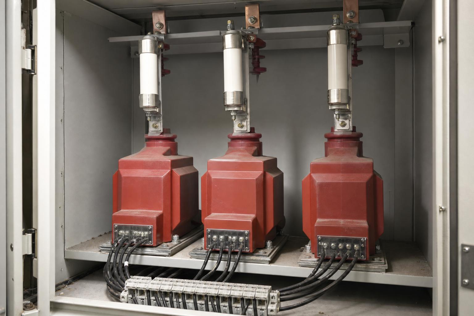
Ferroresonance is a resonance in which a saturating magnetic core turns an ordinary capacitance into a destructive oscillator. It happens when a non-linear inductance — most often a voltage transformer connected phase-to-ground — resonates with the capacitance of cables, lines or grading capacitors in a network that is not solidly earthed. Voltages and currents can exceed nominal values by orders of magnitude, damaging the transformer and disturbing protection. It is not a fault in the ordinary sense: no insulation has failed, no conductor has touched another, and yet the equipment is being destroyed.
For engineers specifying 10–35 kV voltage transformers, ferroresonance is the failure mode that is easiest to dismiss as "a mystery VT failure" and hardest to design out after the fact. This guide explains the mechanism, the switching conditions that trigger it, why prediction is genuinely difficult, and which damping and design measures are available.
What Is Ferroresonance, in Plain Terms?
Resonance between an inductance and a capacitance is predictable when both are linear: the resonant frequency is set by the values, and a safe margin from the supply frequency keeps the circuit out of trouble. Ferroresonance is what happens when the inductance is not linear, because the core saturates.
Once the core saturates, its current-flux characteristic bends, and the resonant frequency is no longer a single number. Resonance can occur at various frequencies, and the circuit can settle into more than one stable operating state. The classic description, credited to Boucherot in 1920, is the coexistence of two stable fundamental-frequency operating points in a series circuit containing a resistor, a non-linear inductor and a capacitor. Modern descriptions extend the same idea to subharmonic, quasi-periodic and chaotic oscillations in any circuit with a saturating inductor.
The practical consequence is that the phenomenon is state-dependent rather than value-dependent. Two networks with identical nameplate data can behave completely differently, because what matters is the sequence of switching events that pushed the core into saturation.
Why Are Voltage Transformers the Usual Suspect?
A voltage transformer is a deliberately weak inductive element. Its rated power is very low because its job is metrology, not power transfer, and nominal primary currents are typically on the order of single milliamperes at several to tens of kilovolts. That design is efficient for measurement and fragile for resonance: the core is small, it saturates at a low flux level, and once saturated it presents a very different inductance to the network.
ABB's engineering note on ferroresonance prevention states the condition directly: ferroresonance can occur when voltage transformers are connected phase-to-ground in an ungrounded network, and the resulting currents can exceed nominal values by orders of magnitude, risking damage to the transformers themselves. The same note records that the phenomenon is initiated by momentary saturation of the core as a result of switching operations, and that the effects are aggravated when damping is insufficient.
Technical literature adds the damage mechanism. Saturation produces significant overcurrents in the windings — mainly in voltage transformers — and those currents lead to thermal damage of the insulation. The same events produce temporary overvoltages and distortion of the phase voltages, so the network sees both a thermal problem inside the transformer and a quality problem across the busbar.
Which Network Conditions Make Ferroresonance Possible?
Ferroresonance needs three ingredients at the same time: a saturable inductance, a capacitance, and a switching or fault event that leaves part of the circuit poorly connected to earth. The IEEE working group on practical aspects of ferroresonance catalogued the circuit arrangements that have been reported in the literature, and the list is a useful checklist for anyone reviewing a distribution design.
| What creates the condition | Where it appears in practice | Why it matters for a 10–35 kV design | |
|---|---|---|---|
| Transformer supplied on one or two phases | Single-phase switching, a blown fuse or a broken conductor leaves the transformer energised through fewer phases than intended | Overhead spur feeds, fused tee-offs, pole-mounted equipment | The most frequently reported arrangement in the literature, and the one most often created by a routine fuse operation |
| Energisation through the grading capacitance of open breakers | An open breaker does not isolate completely at high frequency; its grading capacitance couples the de-energised section to the live side | Substations where a transformer or VT bank sits behind an open circuit breaker | Explains failures during what looked like a normal isolation |
| Voltage transformer on an isolated neutral system | Phase-to-ground VTs provide the only earth reference on an unearthed system, so they see the full zero-sequence excursion | Ungrounded or impedance-earthed 10–35 kV networks, common in the Gulf and Central Asia | The arrangement ABB names explicitly as the classic ferroresonance case |
| Capacitor voltage transformer | The CVT stacks its own capacitor divider on top of the network capacitance | Higher-voltage metering and carrier applications | Adds capacitance in a place that is hard to remove later |
| De-energised line running parallel to an energised line | Capacitive coupling between circuits energises the idle line | Double-circuit overhead lines and cable routes sharing a trench | The idle circuit looks dead but is not at zero potential |
| Transformer on a series-compensated line | The compensation capacitor forms a resonant circuit with the transformer magnetising branch | Transmission rather than distribution | Less common at 10–35 kV, but relevant to upstream studies |
What Does Ferroresonance Look Like on Site?
The event is rarely witnessed directly. What the operator sees afterwards is a set of symptoms that do not quite add up:
- A voltage transformer that has failed thermally with no evidence of a primary fault, often shortly after a switching operation or a fuse operation elsewhere on the feeder.
- Phase voltages that are distorted or displaced, with one phase high and another low, or with a sustained zero-sequence voltage on a system that should be balanced.
- Audible noise and abnormal heating from the VT or the panel, sometimes described as a growl that comes and goes with load.
- Protection operations that cannot be explained by the fault record. Technical literature records protection malfunction among the effects of ferroresonance, alongside the overvoltages and overcurrents.
- Repeated fuse operation on VT circuits where the fuse is being treated as the fault rather than as a symptom.
The diagnostic value of the list is in the correlation. A VT failure on its own is a product question; a VT failure that follows a single-phase switching event on an unearthed network is a system question, and replacing the transformer will not answer it.
Why Is Ferroresonance So Hard to Predict?
Because there is no universal criterion. Research on the subject states plainly that no unambiguous criteria of occurrence and no universal ways to counteract ferroresonance have been defined, and that the risk therefore has to be assessed individually for each network.
Two structural reasons sit behind that conclusion. First, the non-linearity means the response depends on the core's saturation curve, not on a nameplate ratio, so two transformers with the same ratings can behave differently. Second, in many non-transient cases some nodes of the equivalent circuit are electrically floating, or connected to fixed potentials only through very high impedances. A floating node has no defined voltage until something charges it, and what charges it is the transient that started the event.
This is why simulation is used rather than a formula. Studies of damping effectiveness build laboratory-derived models of the damping devices and then simulate the specific network in a transient program, because the answer depends on the configuration, the cable lengths and the switching sequence of that particular installation.
How Is Ferroresonance Damped?
Damping means giving the resonant circuit a path to dissipate energy before the oscillation grows. Three families of measure are used, and they are usually combined rather than chosen exclusively.
Resistive damping across the open delta or the broken delta
A resistor connected across a residual winding loads the zero-sequence circuit and dissipates the oscillating energy. The limitation is arithmetic: a resistor low enough to damp the oscillation is also low enough to draw continuous current from the VT during a genuine earth fault or a sustained system unbalance, which overheats the transformer it is supposed to protect. ABB's note makes exactly this point — resistive damping is not always viable because the low ohmic value required overloads the VT.
Self-adjusting damping elements
The alternative is a damping element whose impedance changes with the condition. ABB describes a two-terminal device that presents a very high resistance during normal system unbalance, so it draws almost no power from the VTs, and lowers its ohmic value when the zero-sequence voltage exceeds a set threshold, damping the oscillation within a small number of cycles. Because the load is applied only when it is needed, the thermal compromise of a fixed resistor disappears, and the device can be applied to practically any IEC-standard inductive medium-voltage voltage transformer.
Network and switching measures
Damping devices treat the symptom. The condition itself is created by the network's earthing arrangement and by how the circuit is switched. Options that are evaluated at design stage include earthing the neutral through an appropriate impedance so that the system is not left isolated, avoiding single-pole switching where the configuration makes it hazardous, and reviewing cable capacitance against the VT magnetising characteristic. None of these is universally correct; each changes the earth-fault current and the protection settings with it.
What Is the Most Common Design Mistake?
Treating the voltage transformer as a component rather than as part of a resonant circuit. The VT is selected for ratio, burden and accuracy class, installed on an unearthed network because that is what the network is, and never analysed together with the cable capacitance and the switching arrangement it will live with.
The second most common mistake is assuming that a damping device is fit-and-forget. Research on commercially available damping devices found that they use control systems with different operating algorithms, and concluded that their parameters must be correctly coordinated with the settings of the power system protection. A damping element that operates during a real earth fault, or that fails to operate because its threshold sits above the actual zero-sequence voltage, is worse than none.
What Should a Specification or RFQ Ask For?
Ferroresonance risk is a system property, but the purchasing documents are where the assumptions get fixed. Four questions are worth putting in writing:
- What is the network earthing arrangement at the point of installation? Ungrounded, resonant-earthed or resistance-earthed changes the answer completely, and the supplier cannot choose a VT design without it.
- Is a residual or broken-delta winding required, and will it carry a damping element? The winding has to exist before a damping device can be connected to it.
- What is the switching arrangement? Single-pole or three-pole, fused tee-off or breaker-controlled, cable-fed or overhead — each combination changes the risk.
- Who is responsible for the ferroresonance study? If the answer is nobody, the risk has been accepted by default rather than by decision.
Nahu Group manufactures voltage transformers for 10–35 kV distribution networks with the winding configurations that residual and damping circuits require, and supplies them with routine test documentation. The voltage transformer range includes indoor and outdoor designs; selection guidance is in the voltage transformer selection guide and the ratios, secondaries and accuracy guide.
How Do You Investigate a Suspected Ferroresonance Event?
Start from the sequence, not from the wreckage. Reconstruct what was switched, in what order, and what the relays recorded in the seconds before the failure. Then check the three ingredients: was the network unearthed at that moment, was there capacitance in the circuit that could resonate with the VT, and did the switching leave a phase open?
If all three are present, the investigation has a mechanism. If one is missing, look for an ordinary insulation failure before accepting a ferroresonance explanation — the term is sometimes used to close a case that a partial discharge test would have explained. A simulation of the reconstructed configuration is the only way to test the hypothesis quantitatively, and it is worth doing before the replacement transformer is installed on the same network.
Frequently Asked Questions About Ferroresonance
What is ferroresonance in simple terms?
Ferroresonance is resonance in a circuit where the inductor has a saturating iron core. Because the core is non-linear, the resonant frequency is not fixed and voltages or currents can reach many times their nominal values, damaging equipment even though no fault has occurred.
Why does ferroresonance usually involve voltage transformers?
A voltage transformer has very low rated power and operates at primary currents of a few milliamperes, so its core saturates easily. When phase-to-ground VTs are the earth reference on an ungrounded network, they sit directly in the resonant circuit.
Does ferroresonance only happen on ungrounded systems?
The classic case is a phase-to-ground VT on an ungrounded network, and that is the arrangement ABB names explicitly. Other arrangements reported in the literature include single-phase supply, energisation through breaker grading capacitance, capacitor voltage transformers and series-compensated circuits.
What triggers ferroresonance?
A transient that momentarily saturates the core. Switching operations are the usual cause, including the operation of a fuse or a single-phase switch that leaves part of the circuit energised through an unintended path.
Can a resistor across the open delta prevent ferroresonance?
It can damp the oscillation, but the value needed is low enough to draw continuous current during a real earth fault, which can overload the voltage transformer. That thermal compromise is why self-adjusting damping elements are used instead.
Is ferroresonance the same as transformer inrush?
No. Inrush is a transient magnetising current that decays as the core settles. Ferroresonance is a sustained or repeatedly re-established oscillation in which the core saturation and the circuit capacitance feed each other.
Can ferroresonance be predicted by calculation?
Not by a single formula. Published research states that there are no unambiguous criteria of occurrence, so the risk has to be assessed for each network, usually by transient simulation of the specific configuration.
What is the first sign of ferroresonance on site?
Distorted or displaced phase voltages and abnormal noise or heating from the voltage transformer, often shortly after a switching operation. A VT that fails thermally with no primary fault is the pattern that should prompt the question.
Sources and Further Reading
- ABB — Ironing out resonance: ferroresonance prevention in MV voltage transformers — the phase-to-ground VT on an ungrounded network, initiation by switching, orders-of-magnitude currents, and the limits of resistive damping
- Energies (MDPI) — Analysis of Ferroresonance Mitigation Effectiveness in Auxiliary Power Systems of High-Voltage Substations — damage mechanisms, the absence of universal criteria, and the need to coordinate damping devices with protection settings
- IEEE Working Group on Practical Aspects of Ferroresonance — Examples of Ferroresonance in a High Voltage Power System — the catalogue of reported circuit arrangements, including single-phase supply, breaker grading capacitance and parallel line coupling
Ferroresonance is one of the few distribution phenomena where the equipment is blamed for a network condition. Understanding the mechanism is what turns an unexplained VT failure into a design decision — damping, earthing arrangement or switching practice — that can be specified, tested and reviewed. For the surrounding network context, see how to read a ring main unit single line diagram and the main types of voltage transformer.
Published October 17, 2026 · Nahu Group (NAHU Electric Technology)