
A voltage transformer — also called a VT or PT, short for potential transformer — is the instrument that steps a dangerous system voltage down to a safe, standard secondary level that meters, relays and controllers can handle. When a buyer searches for a "high voltage voltage transformer", what they usually need is exactly this: a reliable instrument voltage transformer for a high-voltage metering panel, specified with the correct ratio, secondary voltage, accuracy class and burden for their network. Choosing it correctly decides whether your energy metering is billable, whether your protection operates dependably, and whether your panel passes commissioning.
This selection guide walks through the parameters that matter, then shows how they come together in a real export example — Nahu Group's 3×ZNOLP-10M set for CIS / Russian-standard networks. For background on the wider transformer family and its testing, see our companion high-voltage transformers guide.
What a voltage transformer does
In a medium-voltage panel, the busbar might be running at 6 kV, 10 kV, 12 kV or 35 kV. No meter or relay is wired directly to that — the voltage transformer reproduces the primary voltage as a proportional, low-voltage image on its secondary terminals. The measurement instruments are connected to the secondary, and the primary side is protected by fuses, so the dangerous high-voltage circuit and the people working on the panel are kept apart.
A VT serves two broad purposes at once. For metering, it feeds energy meters, power-quality monitors and revenue-accounting systems that must be accurate over the normal operating range. For protection, it feeds voltage relays, directional elements, synchronism-check functions and undervoltage schemes that must respond correctly — and the two duties can demand different accuracy behavior from the same transformer.
Primary voltage and ratio: match the system first
The first selection step is always the system you are connecting to. Confirm the nominal system voltage, the highest system voltage the equipment must withstand, and the frequency. The ratio must then be chosen so the secondary reflects the primary correctly at the standard output voltage. For example, on a 10 kV phase-to-phase system with a 100 V secondary standard, the ratio works out to 10,000/100 V, written as 10/0.1 kV. Never guess the ratio from the panel name alone — check the actual system voltage and whether the VT connects phase-to-phase or phase-to-ground, because that changes the ratio required.
This is where the intent behind searches like "high voltage voltage transformer" often becomes clear: the buyer has a 6, 10 or 35 kV metering panel and needs the correct instrument transformer to make the meters read the real system voltage. Once the primary voltage and connection mode are known, the ratio is a defined quantity rather than a choice.
Secondary windings: 100 V and 100/√3 V standards
The secondary side of a medium-voltage VT is standardized so that any meter or relay from any manufacturer can be connected. The two values you will meet again and again are 100 V and 100/√3 V. A VT connected phase-to-phase — across two lines — normally delivers the line-to-line secondary standard of 100 V. A VT connected phase-to-ground (phase-to-neutral) delivers the phase-to-neutral standard of 100/√3 V, which is the per-phase value of the same 100 V line-to-line system.
Many modern VTs carry both requirements in one design: a primary rated for phase-to-phase voltage with secondary windings of 100 V and 100/√3 V, so the same transformer can serve different wiring arrangements. When you specify, state clearly whether your scheme needs the phase-to-phase output, the phase-to-ground output, or both, and check the secondary configuration against the meter's voltage inputs.
Accuracy class and rated burden
Accuracy class tells you how closely the secondary image matches the true primary voltage. For metering and billing, classes 0.2 and 0.5 are the working standards — class 0.2 means the ratio error stays within 0.2% across its defined range, which is what revenue metering and precise energy management demand. Protection windings use different class designations that guarantee the transformer stays usable under fault conditions, when system voltage can swing far outside the normal band.
Rated burden, expressed in VA, is the load the secondary circuit places on the transformer — the sum of the connected meters, relays, transducers and the wiring between them. A VT selected with too small a burden rating will be pushed outside its accuracy envelope as soon as the instruments are connected, and the meters will record the wrong voltage even though the transformer is mechanically fine. The practical rule is to add up the VA consumption of every device on the secondary circuit, add margin for the connecting cables, and confirm the VT's rated burden covers the total.
Cast-resin or oil, indoor or outdoor
The insulation and construction technology follows the installation. Cast-resin (dry-type) VTs mold the windings in epoxy resin, giving a compact, maintenance-friendly unit that is the standard choice for indoor switchgear and metering panels — no oil to monitor, no leakage risk, and clean handling during installation. Oil-filled or other liquid-insulated designs appear where outdoor exposure, very high voltages or specific utility practices dictate. Alongside construction, confirm whether the unit is rated indoor or outdoor: outdoor service brings UV, rain, pollution and temperature cycling that change the creepage and enclosure requirements.
For panel builders, cast-resin VTs also simplify layout because the bare, resin-encapsulated body can be mounted close to busbars and other components with controlled clearances. If your panel is a standard medium-voltage metering cubicle, a dry-type unit is normally the easiest path to a clean, compact assembly.
System earthing decides phase-to-phase or phase-to-ground ratios
Your network's earthing arrangement determines which VT connection — and therefore which ratio — is correct. On a solidly earthed or effectively earthed system, phase-to-ground connected VTs can be used because the phase-to-neutral voltage is stable and well defined. On an unearthed or impedance-earthed system, a phase-to-ground connected VT can see a full line-to-line voltage on its primary during an earth fault, so either the VT must be rated for that duty or the scheme must connect phase-to-phase instead. This is a design decision to take with the protection engineer, because getting it wrong means either an overstressed transformer or a protection scheme that misbehaves during the very faults it exists to detect.
The VT's own construction supports the answer: a unit with the right insulation level and a secondary available at both 100 V and 100/√3 V can be wired for either philosophy, provided the primary rating matches the voltage it will actually see at its terminals in every operating state.
Export model example: the 3×ZNOLP-10M set
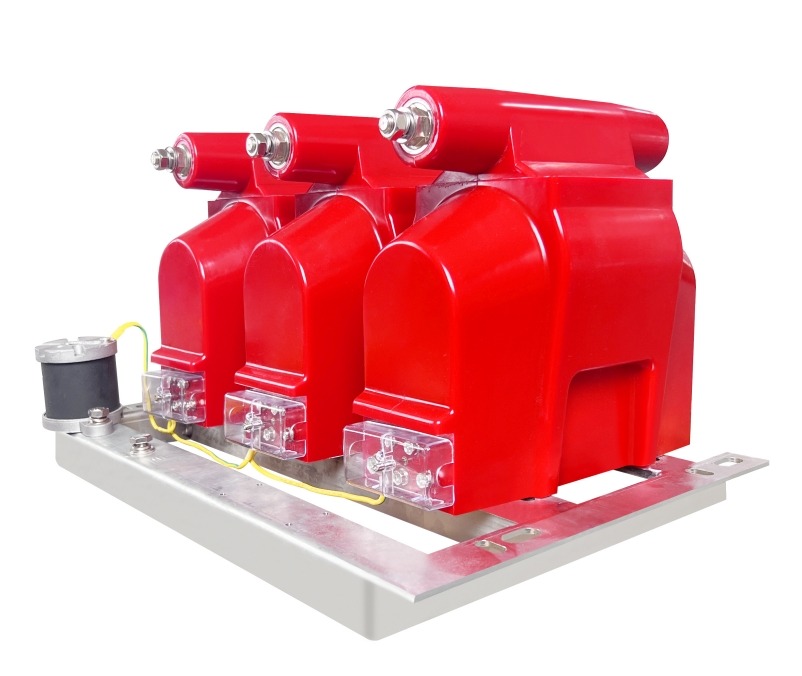
A concrete example ties these parameters together. Nahu Group's 3×ZNOLP-10M is an export-model voltage transformer built for CIS / Russian-standard networks and fully interchangeable with the JDZ10-10R and JDZX10-10R series. It is a cast-resin (dry) design supplied as a set of three single-phase units for three-phase panel metering, covering a rated voltage range of 3–12 kV. It provides standard 100 V and 100/√3 V secondaries for Russian-standard panel metering and protection schemes, with accuracy classes 0.2 and 0.5. Details are on the 3×ZNOLP-10M voltage transformer product page.
Why a three-unit set? A three-phase panel needs a voltage image on all three phases for three-phase metering and for protection functions such as undervoltage and directional elements. Supplying three matched single-phase units lets the panel builder install them in the positions dictated by the busbar arrangement, and each unit is individually interchangeable with its Russian-standard counterpart, which simplifies replacement stock for operators maintaining JDZ10-10R or JDZX10-10R panels.
In a typical panel metering application, the set connects to a 6 or 10 kV busbar through primary fuses, the 100 V or 100/√3 V secondaries feed the multifunction meter and the protection relay, and the secondary circuit is earthed at one point per the wiring diagram. The metering class 0.2 winding carries the revenue meter; if a second class 0.5 or protection winding is available, the relay is fed from it so the two duties never load each other. The result is a panel that commissions cleanly and meters accurately for years.
Compliance and manufacturer support
Finally, confirm the transformer is designed and tested to the standard your market expects. For instrument transformers, that means IEC 61869 compliance covering accuracy, insulation and thermal performance, verified by type tests on the actual design. Nahu Group (NAHU Electric Technology) manufactures under an ISO 9001 quality system with IEC 61869-compliant designs, has exported since 2008 to customers in 40+ countries, and covers a product range spanning 3–40.5 kV — so the selection process above can be followed for everything from a 10 kV metering panel to a 35 kV substation.
When you are ready to specify, prepare four numbers before contacting a supplier: the system voltage, the required ratio, the secondary voltage or voltages, and the accuracy class with its burden in VA. With those, any engineer can confirm the correct cast-resin voltage transformer — or a 3×ZNOLP-10M export set — for your panel. Browse the full voltage transformers range or send your panel drawings to our engineering team for a ratio and class check.
Published September 2, 2026 · Nahu Group (NAHU Electric Technology)