
An electrical transformer is a static electrical machine that changes the voltage of an alternating current supply, at constant frequency, by electromagnetic induction between two or more windings coupled by a magnetic core. That single idea carries an entire power system.
This page is the hub for our transformer cluster: the working principle, the turns ratio formula with a worked example, the parts and components, core type versus shell type construction, the main types and their functions, what a circuit diagram shows, and how to specify a unit for a project. Transformers sit at every boundary of an electrical network, and the same physics covers a 500 MVA grid unit and a 10 VA instrument transformer — only the construction, cooling and insulation change.
What is an electrical transformer?
Anyone asking what is transformer operation in plain terms can start here: two windings share one magnetic core, and only a changing flux transfers energy between them. An electrical transformer is a device with two or more insulated windings linked by a common magnetic circuit. Alternating current in the primary winding produces an alternating flux in the core; that flux links the secondary winding and induces a voltage in it. The windings are electrically separate but magnetically coupled, so a transformer changes voltage level and can provide galvanic isolation at the same time.
Three consequences follow, and all three matter in every specification discussion:
- Power in equals power out, less losses. An ideal transformer transfers the same apparent power, so a step-up in voltage always comes with a step-down in current in the same ratio.
- Frequency is unchanged. Only voltage and current are transformed; a 50 Hz supply stays 50 Hz on both sides.
- The ratio is fixed by design. Turns set it. Taps only trim it, so they cannot turn a distribution transformer into a transmission transformer.
This is the dividing line between the two families most often confused. A power transformer moves real power to a load and is rated in kVA or MVA. An instrument transformer reproduces system voltage or current as a small, standardised signal for meters and protective relays, and is rated by burden.
How does an electrical transformer work?
The working principle of transformer action is electromagnetic induction, described by Faraday's law: a voltage is induced in a conductor whenever the magnetic flux linking it changes. In a transformer the changing flux is produced deliberately by the alternating supply current, and the conductor is the secondary winding.
- Alternating voltage applied to the primary winding drives an alternating current, and the laminated steel core carries the flux: a low-reluctance path makes most of it link both windings instead of leaking into air.
- The changing flux induces a back-EMF in the primary and an EMF in the secondary, each proportional to the rate of change of flux and to that winding's number of turns.
- Secondary current flows only when a load is connected, and the flux it produces is balanced automatically by the primary current — which is why a loaded transformer draws more current.
For a sinusoidal supply the transformer EMF equation is E = 4.44 f N Φm, where E is the RMS induced voltage, f is frequency, N is turns and Φm is peak core flux. Two consequences follow. At fixed voltage and frequency the core flux is essentially constant from no load to full load, which is why core loss is treated as a fixed loss. And if frequency falls while voltage is held, flux must rise, so a 50 Hz transformer should not be run at 60 Hz at the same voltage.
A solid core would carry flux, but the alternating flux would drive circulating eddy currents inside the steel and heat it; laminating the core into thin insulated sheets breaks those paths. Those eddy currents and hysteresis are the two core losses present whenever the unit is energised.
What is the transformer turns ratio formula and how do you use it?
The transformer formula links voltage and turns. For an ideal transformer the primary voltage relates to the secondary voltage exactly as the primary turns relate to the secondary turns:
Vp / Vs = Np / Ns
The same ratio applies, inverted, to current, because power is conserved. With a = Np / Ns: Vs = Vp / a and Is = Ip × a. When a > 1 the unit steps voltage down; when a < 1 it steps voltage up.
Worked example: turns ratio calculation
A distribution transformer rated 11,000 V primary and 400 V secondary with 40 secondary turns has a turns ratio of a = 11,000 / 400 = 27.5, so Np = 27.5 × 40 = 1,100 turns. Check it with a load: at 250 kVA the secondary current is 250,000 / 400 = 625 A and the primary current is 250,000 / 11,000 = 22.7 A. The current ratio, 625 / 22.7 = 27.5, is the voltage ratio inverted — the power balance working as expected.
The same logic scales instrument transformers: a voltage transformer with an 11,000 V / 100 V ratio has a = 110, so a 100 V secondary reading represents 11 kV on the primary. Accuracy class, burden and secondary connections are covered in our voltage transformer selection guide.
What are the transformer parts and components inside an electrical transformer?
Whatever the rating, every transformer contains the same functional blocks.
Magnetic core
The core is the magnetic circuit that links the windings, built from thin insulated laminations stacked and clamped, or wound into a toroidal or C-core assembly on smaller units. Core material, lamination thickness and any air gap decide the magnetising current and the core loss.
Transformer winding: primary and secondary coils
The primary winding takes the supply and the secondary winding delivers the transformed voltage to the load. A transformer winding is copper or aluminium conductor insulated with enamel, paper or cast resin according to the temperature class and environment. Distribution units commonly use layer windings with a sheet or strip low-voltage winding close to the core; larger power transformers use disc windings, which better withstand short-circuit forces.
Insulation system, tank and cooling
Insulation is a system, not a single part: conductor enamel, inter-turn and inter-layer insulation, barriers between windings, and the bushing and lead insulation that carries the connection out. It must withstand rated voltage continuously, plus impulse overvoltages and short-circuit forces. A liquid-immersed transformer sits in a steel tank of insulating oil that insulates the active part and carries heat to the tank walls, with radiators or fans on larger units. A dry-type transformer has no liquid: windings are cast in resin and cooled by air, which suits indoor installation close to the load.
Bushings, tap changer and protection
Bushings bring the winding leads through the tank or enclosure; they must hold voltage stress across their surface and through their body, so creepage distance and pollution class matter outdoors. Insulated bushings for alternating voltages above 1,000 V are covered by IEC 60137. A tap changer selects a different number of primary turns to correct a supply that is persistently high or low: an off-circuit tap changer is operated with the unit de-energised, while an on-load tap changer switches under load. The protection package can include temperature sensors, Buchholz or sudden-pressure relays, pressure relief devices, oil level gauges, breathers and surge arresters, together with the instrument transformers that feed relays and meters.
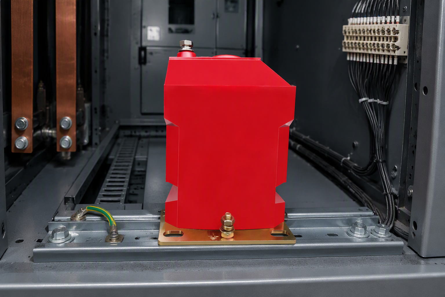
What is the construction of a transformer: core type vs shell type?
Transformer construction is described first by how the magnetic core and the windings are arranged relative to each other, and second by how the active part is insulated and cooled. The two classic answers to the construction of transformer cores and coils are core type and shell type.
Core type construction
The core is a closed framework of limbs and yokes, and the windings are wound around the limbs, so the core is largely enclosed by the coils. The windings are normally concentric cylinders, low voltage nearest the core and high voltage outside. This gives good access for insulation and cooling ducts, which is why most large power transformers are core type.
Shell type construction
The magnetic circuit wraps around the windings instead: laminations form a shell on both sides of the coils, which are usually flat pancake or sandwich coils around a central limb. This shortens the mean magnetic path and gives strong mechanical support against short-circuit forces, which suits low-voltage high-current designs and some instrument transformers.
| Feature | Core type transformer | Shell type transformer |
|---|---|---|
| Core and winding arrangement | Windings surround the core limbs | Core surrounds and supports the windings |
| Winding shape | Concentric cylindrical coils | Sandwich or pancake coils |
| Magnetic circuit | Limb and yoke frame, one flux path per limb | Two parallel flux paths, central limb carries the windings |
| Insulation and cooling | Easier to insulate and to duct for cooling | More compact core, tighter clearances |
| Short-circuit strength | Good when adequately braced | Very good, inherent mechanical support |
| Typical use | Power and distribution transformers of larger rating | Low-voltage high-current units and some special transformers |
The second construction decision is the insulation and cooling medium. An oil-immersed unit carries large ratings efficiently but needs oil containment, bunding and fire separation. A dry-type unit has no liquid to leak, pool or burn and is normally installed indoors close to the load. Both are specified against the same IEC 60076 series.
What are the different types of transformer?
Type names are built from four independent questions: what the transformer does, how it is constructed, how many phases it serves, and how it is insulated. One unit can therefore be described honestly as a three-phase, oil-immersed, distribution, step-down transformer. The table is the routing view.
| Type | Function | Typical application | Go deeper |
|---|---|---|---|
| Power transformer | Transfers bulk power between voltage levels | Generation step-up, transmission substations | Types of transformers |
| Distribution transformer | Steps medium voltage down to utilisation voltage | Pole-mounted and pad-mounted distribution | Types of transformers |
| Three-phase transformer | Serves a complete three-phase system in one unit | Industrial supply, substations, large buildings | 3-phase transformers |
| Instrument transformer | Reproduces system voltage or current as a scaled signal | Metering, protection and control | CT basics |
| Autotransformer | Changes voltage using one winding with a tapped section | Voltage regulation where isolation is not required | Types of transformers |
| Isolation transformer | Separates two circuits, usually at or near 1:1 | Equipment protection and noise reduction | Types of transformers |
Three routing decisions cover most of the taxonomy. For what the families are and how they differ, work through the full guide to the different types of transformers. For a three-phase project, the phase and core arrangement is answered in the post on the 3-phase transformer. If the type is settled and you need the winding connection for a vector group, the delta and wye transformer connections post covers delta, wye, zigzag and the common vector groups, the voltage transformer choice guide owns accuracy class and burden, and the basics of current transformers post covers the CT side.
For measurement and protection hardware, Nahu Group manufactures current transformers, voltage transformers and metering equipment for distribution networks and substations — the equipment most often specified alongside the switchgear in which these transformers are installed.
What is the function and purpose of a transformer?
The primary function of transformer equipment is to change AC voltage and current while transferring power, so each part of a system can operate at the voltage and current that suits it. That one capability creates three purposes.
- Economical transmission and usable voltage levels. Line losses rise with the square of current, so transmitting at high voltage and low current cuts losses and conductor cross-section. Step-up transformers make that possible at the generation end; step-down and distribution transformers then deliver the power at the voltage machines, lighting and electronics need.
- Galvanic isolation and system earthing. Separate windings let a transformer isolate two circuits while transferring power, which is used for safety, for separating system earths and for limiting fault energy. Zigzag earthing transformers go further and create a neutral point in an otherwise unearthed system, so earth fault protection works correctly.
- Measurement and protection. Voltage and current transformers scale system quantities down to levels meters, transducers and relays can accept, and isolate instrumentation from the primary system. Measurement is normally delivered as an assembly — instrument transformers, fusing, isolation links, wiring and terminals — in the units catalogued as metering boxes and metering units.
What does a transformer circuit diagram show?
A transformer circuit diagram is a schematic, not a drawing of the hardware. It shows how the windings relate to the source, the load and the protection devices, and omits the physical arrangement inside the tank. In a full schematic the transformer is two coils either side of parallel lines representing the laminated core. The symbols to read are:
- Two coupled coils and the core, identifying the windings and confirming that the coupling is magnetic, not electrical.
- Polarity dots, marking the winding ends whose induced voltages are in phase — the detail that makes parallel operation and differential protection correct rather than reversed.
- The source and the load, showing which side is primary and therefore which way the voltage is transformed.
- Protective devices and earthing: fuses, circuit breakers, surge arresters, the shorting link across a current transformer secondary, the fuse in a voltage transformer secondary circuit, and where the secondary neutral or instrument circuit is earthed.
How do you select an electrical transformer for a project?
Selection is a sequence of decisions, and the order matters, because a late change in ratio or vector group can invalidate the mechanical design. Work through these groups and the specification writes itself.
1. Electrical data to fix first
Rated power in kVA or MVA from the calculated maximum demand plus a stated allowance for growth; primary and secondary rated voltages, saying whether each is phase-to-phase or phase-to-ground; phases and frequency; connection arrangement and vector group, which fix the phase displacement between windings; impedance or short-circuit voltage, which sets the fault level the switchgear must withstand; and tap range.
2. Losses, efficiency and cost of ownership
No-load loss is present whenever the unit is energised and is set mainly by core material and flux density; load loss varies with the square of load current and is set mainly by conductor cross-section. Efficiency is high at rated load but falls at light load, because core loss does not follow the load — which is why an oversized transformer is not automatically the better choice. If a project specifies a loss limit, that limit belongs in the enquiry, because it changes the core and winding design.
3. Environment, cooling and installation
Confirm the location, ambient temperature range, altitude, ingress protection requirement, noise limit, and the clearances needed for cooling and for cable or busbar connections. Coastal, humid, dusty or polluted environments and seismic requirements all influence enclosure and bushing selection.
4. Instrument transformers: accuracy class and burden
For a voltage transformer or current transformer the quantity to size is not power but burden: add up the VA of every meter, relay, transducer and the secondary wiring itself, then compare it with the rated burden for the accuracy class you need. A metering class is chosen for revenue accuracy and a protection class for the relay and fault conditions it must reproduce; a unit qualified for one should not be specified for the other. The current transformers and voltage transformers ranges show how ratios, secondaries and accuracy classes appear on a datasheet.
Frequently asked questions about electrical transformers
What is an electrical transformer?
An electrical transformer is a static device with two or more insulated windings linked by a magnetic core. Alternating current in the primary winding creates a changing flux in the core, which induces a voltage in the secondary winding. It changes voltage and current levels at unchanged frequency.
How does a transformer work?
By mutual induction. The alternating primary current produces an alternating magnetic flux in the laminated core, that flux links the secondary winding, and because it is changing it induces a voltage there. The voltage induced in each winding is proportional to its number of turns, so the turns ratio sets the voltage ratio.
What is the turns ratio of a transformer?
It is the number of primary turns divided by the number of secondary turns, and for an ideal transformer it equals primary voltage divided by secondary voltage. A unit with 1,100 primary turns and 40 secondary turns has a ratio of 27.5, so 11,000 volts on the primary produces 400 volts on the secondary.
Can a transformer change DC voltage?
No. A conventional transformer needs a changing magnetic flux to induce voltage, and steady direct current produces a steady flux, so nothing is induced in the secondary. Direct current conversion needs a DC to DC converter, and DC measurement a suitable transducer.
What is the difference between a power transformer and a distribution transformer?
The difference is the role in the network. A power transformer transfers bulk power between transmission voltage levels and is rated in megavolt-amperes. A distribution transformer steps medium voltage down to the utilisation voltage used by feeders, buildings and equipment, and is rated in kilovolt-amperes.
How do you size a transformer for a load?
Start from the calculated maximum demand in kilovolt-amperes rather than summed motor nameplate ratings, then allow for load growth and duty cycle. Check the rating at the actual ambient temperature and altitude, confirm the impedance against the downstream fault rating, and verify the ratio and tap range against the supply.
Sources and further reading
- IEC 60076-1:2011 — Power transformers, Part 1: General — general requirements for power transformers, including the rating terms used here
- Faraday's Law — HyperPhysics, Georgia State University — the induction relationship behind the transformer working principle
- Guide to transformer windings and coils — Maddox technical library — how primary and secondary windings, tap leads, layer windings and disc windings are built
Need a transformer specification checked?
Send the rated power, primary and secondary voltage, phase and frequency, connection arrangement, impedance and tap range, together with the installation environment. Nahu Group will confirm a suitable model and the drawings, nameplate data and test documentation your engineers need.
Browse the rest of our transformer library on the technical blog or start from the full electrical equipment range.
Published September 22, 2026 · Nahu Group (NAHU Electric Technology)