
There are many different types of transformers, but the two that matter most are the step-up transformer, which raises voltage, and the step-down transformer, which lowers it — every other design, from a grid-scale power transformer to a small instrument transformer, is a variation on one of those two jobs.
The vocabulary is the problem. Manufacturers, specifiers and distributors all use overlapping labels — power, distribution, isolation, instrument, dry-type, oil-immersed, core, shell — and products carrying different labels are often compared as if they were substitutes. They are not. A metering voltage transformer cannot replace a distribution transformer, and an oil-immersed unit is not an option for a switchgear cubicle indoors.
This article classifies the families the way an electrical engineer actually works through them: first by what the transformer does to the voltage, then by how it is built and cooled, then by the application it is installed into, and finally by the instrument transformers used for metering and protection. If you want the underlying physics before the taxonomy, our companion guide to electrical transformers basics covers induction, windings and the turns-ratio formula; this page stays at the classification level.
Looking for a specific transformer type?
Send the application, system voltage, ratio, phase configuration, installation environment and required documentation — we will confirm a suitable type and the drawings your engineers need.
What are the 2 main types of transformer?
The 2 types of transformer that answer this question are the step-up transformer and the step-down transformer. The distinction is the direction of the voltage change, and it follows directly from the turns ratio: a transformer with more turns on the secondary than on the primary raises voltage, and one with fewer secondary turns lowers it. In an ideal transformer the secondary voltage is proportional to the primary voltage by the ratio of secondary to primary turns.
Nothing about the hardware forces a device to be one or the other. A transformer is a bilateral device: the winding that is energised defines which side is the primary, so a unit that steps 11 kV down to 400 V can, in principle, step 400 V up to 11 kV if it is fed from the low-voltage side. In practice, insulation levels, tapping arrangements and design assumptions mean the two directions are not equally rated, and the nameplate is written for the intended duty.
| Feature | Step-up transformer | Step-down transformer |
|---|---|---|
| Effect on voltage | Raises the voltage from primary to secondary | Lowers the voltage from primary to secondary |
| Winding relationship | Secondary turns exceed primary turns | Secondary turns are fewer than primary turns |
| Effect on current | Secondary current is lower than primary current | Secondary current is higher than primary current |
| Power throughput | Essentially unchanged apart from losses | Essentially unchanged apart from losses |
| Typical position in a system | Generator output, transmission end of a feeder | Substation and distribution level, equipment supply |
| Typical example | Generator step-up transformer at a power station | Distribution transformer feeding a low-voltage network |
What are the different types of transformers by function?
Function is the second classification axis, and it is the one that decides what the transformer is allowed to be connected to. All types of transformer transfer energy by electromagnetic induction, but their rated duty, insulation coordination and intended connections differ, which is why a specification written for one category should not be reused for another.
| Transformer type | Main function | Typical application |
|---|---|---|
| Power transformer | Transfers bulk power between voltage levels | Generation and transmission substations |
| Distribution transformer | Steps medium voltage down to utilisation voltage | Overhead, pad-mounted and packaged distribution networks |
| Isolation transformer | Separates two circuits galvanically without an intended voltage change | Safety isolation, noise and ground-loop separation, sensitive equipment supply |
| Autotransformer | Changes voltage using a single tapped winding | Voltage adjustment, motor starting, interconnections where isolation is not required |
| Instrument transformer (CT and VT) | Scales current or voltage down for meters and protective relays | Metering, protection and control in switchgear and substations |
| Special-purpose transformer | Performs a defined industrial duty | Furnace, rectifier, traction, welding and testing applications |
Two entries in that table are routinely confused. A power transformer and a distribution transformer are both built to move real power, and the boundary between them is a matter of system role rather than a single fixed rating: the power transformer sits at the bulk-transfer point, while the distribution transformer sits at the point where the network meets the load. An autotransformer is different again — because primary and secondary share one winding, it needs less material for the same throughput, but it provides no galvanic isolation between the two sides.
What are the different types of transformers by construction and cooling?
Construction and cooling decide where a transformer may be installed, how it is maintained and what documentation a project will demand. Three distinctions do most of the work: core versus shell, single-phase versus three-phase, and dry-type versus liquid-immersed.
Core type or shell type?
In a core-type transformer the windings surround the limbs of the magnetic core, so the magnetic circuit is largely inside the coils. In a shell-type transformer the arrangement is inverted: the laminated core surrounds and supports the windings, providing a mechanical shell around the coils. Core-type construction is the more common choice for general power and distribution duty because it is easier to wind and to cool; shell-type designs are used where mechanical robustness and a compact magnetic circuit are prioritised. Either way, the core is almost always laminated to limit eddy-current loss, and grain-oriented silicon steel is the usual material, with amorphous cores chosen where no-load loss matters most.
Dry-type or oil-immersed?
In a dry-type transformer the insulation system is solid and air-cooled — cast resin, vacuum-pressure impregnated, or open-wound with insulating barriers. In an oil-immersed transformer the active part is submerged in an insulating liquid, normally mineral oil or an ester, which insulates the windings and carries heat to the tank surface. Cooling designations you will see on datasheets follow the same convention: AN and AF for air-natural and air-forced dry-type units, ONAN and ONAF for oil-natural and oil-forced units.
Dry-type transformers are the usual choice indoors, inside switch rooms and tunnels, and anywhere a liquid spill or a pool fire would be unacceptable. Oil-immersed transformers remain the better answer for larger ratings and for arduous duty cycles, because the liquid moves heat far more effectively — but they bring oil containment, fire separation and routine oil testing with them. Note the standards architecture too: dry-type power transformers are covered by IEC 60076-11, whose scope explicitly excludes instrument transformers, which are handled by the separate IEC 61869 series.
| Feature | Dry-type transformer | Oil-immersed transformer |
|---|---|---|
| Insulation and cooling medium | Air, with cast resin, vacuum-pressure impregnation or open windings and barriers | Insulating liquid — typically mineral oil or an ester — that both insulates and transfers heat |
| Typical installation | Indoors: switch rooms, buildings, tunnels, plant rooms | Outdoors in a compound, or indoors with bunding and fire separation |
| Fire and environmental considerations | No liquid to leak or pool; preferred where fire load is a constraint | Requires oil containment, spill control and fire separation |
| Common cooling designations | AN, AF | ONAN, ONAF |
| Typical rating band | Most common at distribution and medium-voltage levels | Preferred for larger power ratings and heavy overload duty |
| Condition monitoring | Visual, thermal and partial-discharge checks; windings are visible | Oil sampling — dissolved gas analysis, moisture and dielectric strength |
| Standards reference | IEC 60076-11 (dry-type power transformers) | IEC 60076-1 (general power transformer requirements) |
What are the different types of transformers by application?
Classifying by application is the quickest way to narrow a shortlist, because the installation environment usually rules out whole families before any electrical parameter is considered.
- Generation and transmission. Large power transformers, including generator step-up units, connect stations to the transmission network at the highest system voltages.
- Substation and distribution. Distribution transformers, pole-mounted or pad-mounted, bring voltage down to the level that feeders and customers actually use.
- Industrial and commercial plant. Dry-type transformers are typically installed inside the building to supply motor control centres, converters and process equipment.
- Safety and power quality. Isolation transformers separate circuits, break ground loops and reduce common-mode noise on sensitive loads.
- Voltage adjustment. Autotransformers and regulating transformers trim voltage without providing isolation.
- Metering and protection. Instrument transformers scale the quantities that meters, transducers and relays are designed to accept.
The same unit type can appear in more than one row, but the application fixes the constraints that follow: enclosure rating, altitude and seismic class, pollution level, and the accuracy or protection performance that has to be demonstrated in test documentation.
What are the different types of instrument transformers?
Instrument transformers are the measurement branch of the family, and they divide cleanly into three kinds of transformer: current transformers, voltage transformers, and combined units that do both. Their job is not to move power but to reproduce a high voltage or a large current at a magnitude that standard meters and relays can accept, while keeping the measurement circuit isolated from the primary system. The family is governed by the IEC 61869 series.
Current transformers (CT)
A current transformer is installed so that the primary conductor carries the current being measured — often the conductor passes straight through the core as a single primary turn. The secondary delivers a scaled current, commonly 1 A or 5 A, to meters, transducers or protective relays. CTs are specified for two different duties: metering cores are selected for accuracy at normal operating current, while protection cores are selected for performance during faults. A conventional CT with an energised primary must never be left with an open secondary, because dangerous voltages can develop across the open terminals.
Voltage transformers (VT / PT)
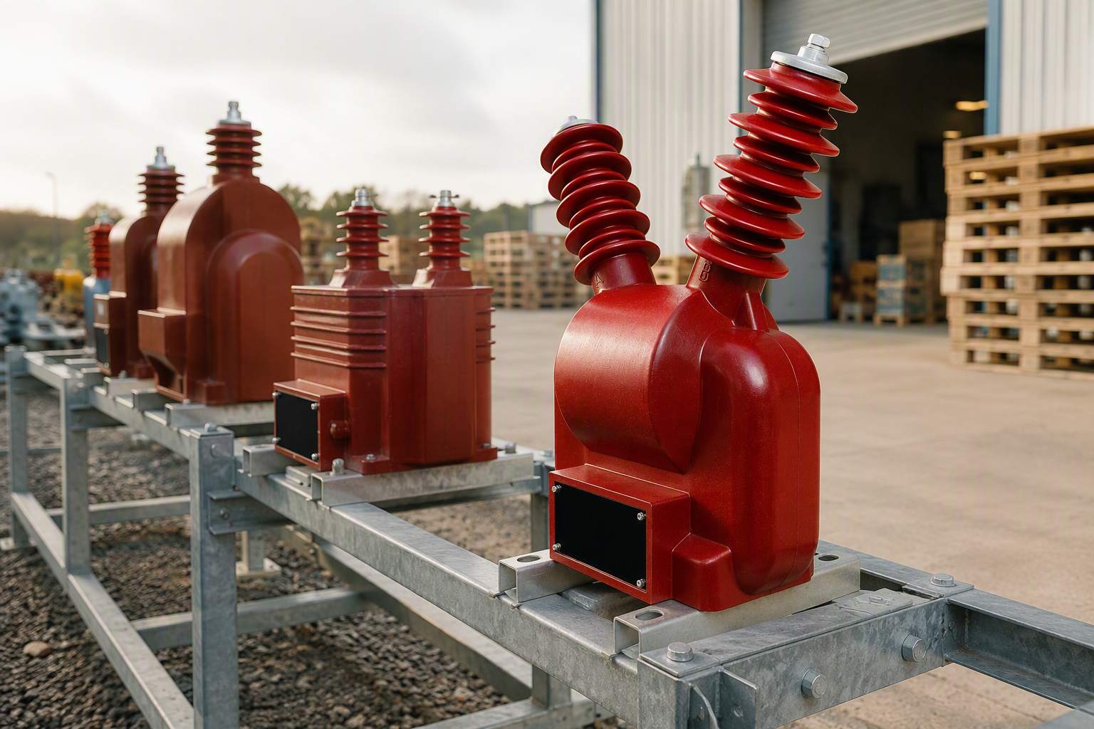
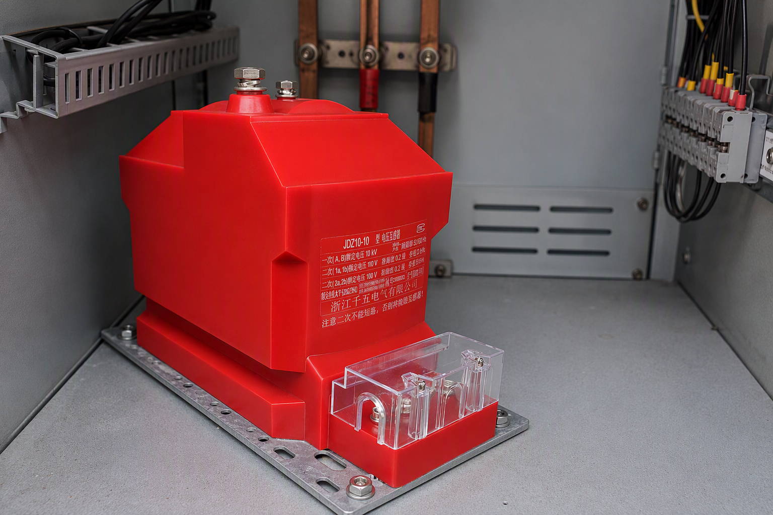
A voltage transformer, also called a potential transformer, is connected across the voltage being measured and produces a reduced secondary voltage, typically 100 V or 110 V. Inductive voltage transformers are the standard solution at distribution and medium-voltage levels and are often cast in resin for indoor switchgear; capacitive voltage transformers are used at transmission voltages, where a capacitive divider feeds an electromagnetic secondary stage. You can see the two product families side by side in our range of current transformers for metering and protection and voltage transformers for electrical measurement.
Combined and special instrument transformers
Where panel space is tight, a combined instrument transformer packages a current transformer and a voltage transformer in a single housing with shared primary insulation. Low-power instrument transformers and electronic current or voltage transformers represent a further branch, producing a low-energy or digital secondary signal for modern substation automation.
How do you choose the right type of transformer?
Work from the application inward, and confirm each point against the applicable standard and the manufacturer's documentation rather than relying on a general description of the product category.
- Voltage and ratio. Fix the primary and secondary voltages, the ratio and the frequency, and state whether the figures are phase-to-phase or phase-to-ground.
- Duty and rating. Decide whether the transformer moves power or provides a measurement signal. A power duty needs a kVA rating and a load profile; a measurement duty needs an accuracy class and a burden.
- Construction and cooling. Choose dry-type or oil-immersed from the installation location and the fire and spill constraints, then confirm the cooling designation.
- Configuration. Confirm single-phase or three-phase, the connection arrangement, and for instrument transformers how many cores and windings are required.
- Isolation. If the circuit needs galvanic separation, an autotransformer is the wrong family regardless of the ratio.
- Environment. Indoor or outdoor, ambient temperature, altitude, humidity, pollution and seismic requirements all change the specification.
- Documentation. Ask for the datasheet, drawings, routine test records and declarations for the exact model, not for the product family in general.
NAHU Electric builds current transformers, voltage transformers and metering equipment for grid and industrial projects, so if two categories look interchangeable on paper, a short technical exchange usually settles it faster than another round of datasheet comparison. Nahu Group can also confirm which drawings and test documentation a given specification will require.
Frequently asked questions about different types of transformers
What are the 2 main types of transformer?
The two main types are the step-up transformer and the step-down transformer. A step-up transformer has more turns on the secondary than on the primary and raises voltage; a step-down transformer has fewer secondary turns and lowers voltage. Both transfer power by electromagnetic induction, and the secondary voltage is proportional to the primary voltage by the ratio of turns.
What are the different types of transformers classified by construction?
By construction, transformers are usually divided into core type, in which the windings surround the core limbs, and shell type, in which the laminated core surrounds the windings. They are then divided again by phase configuration — single-phase or three-phase — and by the insulation system, which separates dry-type units from liquid-immersed units.
What is the difference between a dry-type and an oil-immersed transformer?
A dry-type transformer uses solid insulation with air cooling, so there is no liquid to leak, pool or burn; it is normally installed indoors. An oil-immersed transformer uses an insulating liquid that both insulates the windings and transfers heat, which suits larger ratings and heavy duty cycles but requires oil containment, fire separation and routine oil testing.
What is the difference between a power transformer and a distribution transformer?
The difference is system role. A power transformer transfers bulk power between transmission voltage levels and sits at the generation or substation end of the network. A distribution transformer sits at the point where the network meets the load and steps medium voltage down to the utilisation voltage that feeders, buildings and equipment use.
What are the different types of instrument transformers?
Instrument transformers are current transformers, which reproduce system current as a scaled secondary current, and voltage transformers, which reproduce system voltage as a reduced secondary voltage. Combined instrument transformers package both functions in one housing. All of them isolate meters, transducers and protective relays from the primary system, and the family is covered by the IEC 61869 series.
What is the difference between an autotransformer and an isolation transformer?
An autotransformer has a single winding with a tapped section, so primary and secondary share the same winding and no galvanic isolation exists between them. An isolation transformer has separate primary and secondary windings and exists precisely to provide that separation, typically at or near a 1:1 ratio, together with a chosen level of noise and ground-loop isolation.
How do you choose the right type of transformer for an application?
Start with the voltage and ratio, then decide whether the duty is power transfer or measurement, then choose the construction and cooling from the installation environment. Confirm the phase configuration and connection arrangement, check whether galvanic isolation is required, and finish by requesting the datasheet, drawings and routine test documentation for the exact model rather than for the product family.
Sources and further reading
- IEC 60076-11:2018 — Power transformers, Part 11: Dry-type transformers — the product standard for dry-type power transformers, including their climatic, environmental and fire-behaviour classes; its scope explicitly excludes instrument transformers
- IEC 61869-1:2023 — Instrument transformers, Part 1: General requirements — the product family standard for instrument transformers above 1 kV AC, covering error limits and type, routine and commissioning tests
- IEC 61869-2:2012 — Instrument transformers, Part 2: Additional requirements for current transformers — the specific product standard for inductive current transformers used with measuring instruments and protective devices
Still working through the families? Our companion posts cover the device itself in electrical transformer and the operating principle in electrical transformers basics.
Published September 22, 2026 · Nahu Group (NAHU Electric Technology)