
A current transformer is only accurate into the burden it was rated for, and the burden is decided by three things the datasheet cannot know: how far the relay is, how thick the secondary cable is, and how hot the panel gets. This is why two installations with identical CTs and identical relays can behave completely differently, one reading true and the other reading low exactly when the fault current matters.
The calculation is arithmetic, not simulation, and it takes ten minutes. What follows is the full budget: every device on the loop, the lead resistance worked out from length and cross-section, a concrete example at 5 A and at 1 A, and the symptoms that tell you the budget has been exceeded before a test set ever arrives on site.
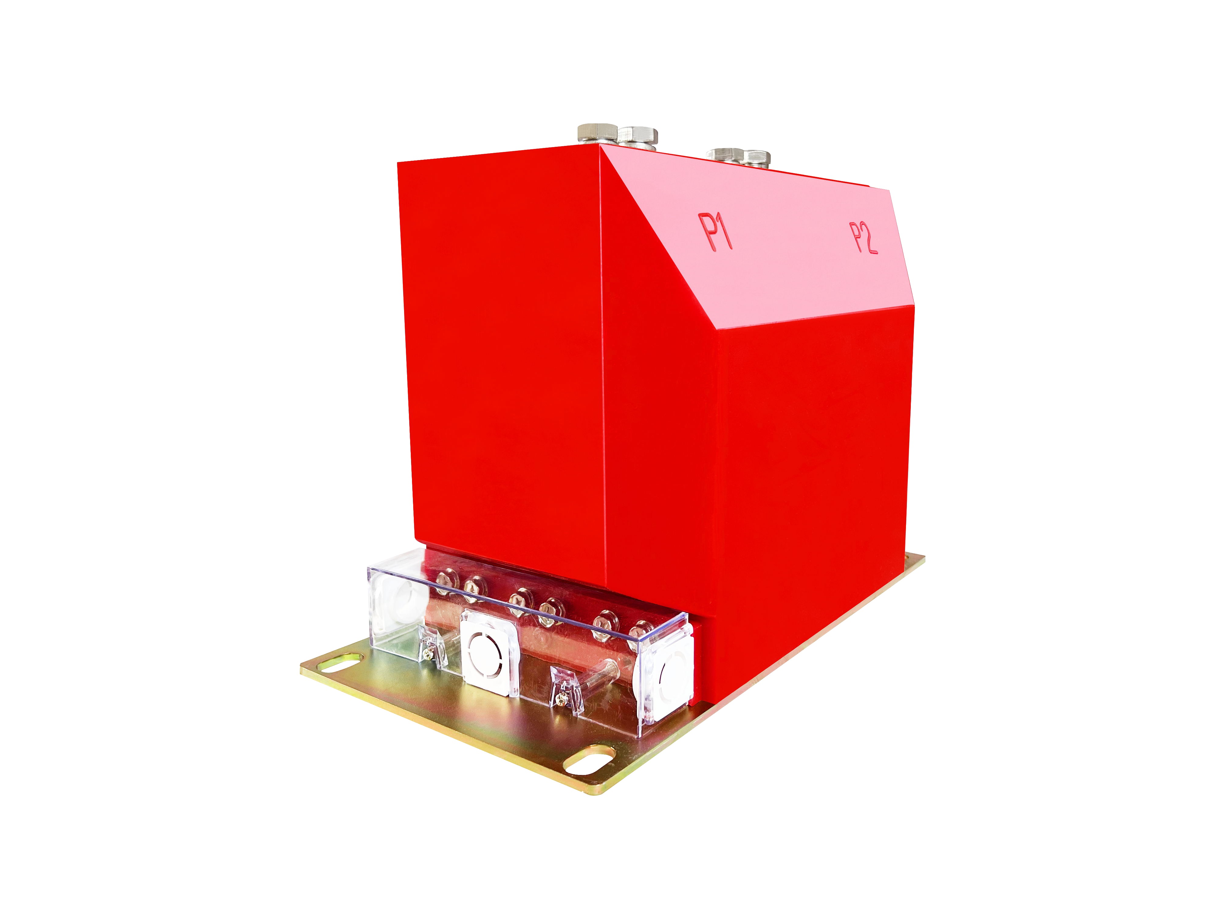
What Does CT Burden Actually Mean?
Burden is the impedance of everything connected to the secondary, expressed as volt-amperes at rated secondary current. A 15 VA CT with a 5 A secondary can drive 15 VA into its loop and still meet its accuracy class; the same CT driving 35 VA is operating outside its specification and will saturate earlier than the nameplate suggests.
The subtlety is that burden is not a single number, it is a sum that changes with the installation. The CT is tested with a resistive or inductive burden at a stated power factor. The real loop is part resistance (cable, terminals) and part inductance (relay coils, meters), and modern digital relays present almost no burden at all, which shifts the mix towards the resistive part.
For protection CTs the consequence of exceeding the burden is not a small metering error. A protection CT is specified to stay within a composite error at a stated accuracy limit factor, which is the multiple of rated current it can transform into rated burden. Raise the burden and that factor falls, so the CT saturates at a lower multiple of primary current and the relay sees a fraction of the fault it should.
The VA Budget: Every Device in the Loop
List the devices first, because they are the part you can read from datasheets. Then add the wiring, which is the part you have to calculate. The total, with a margin, is the burden the CT must be rated for.
| Item | Typical burden | Note |
|---|---|---|
| Digital protection relay, current input | 0.1 to 0.5 VA | Per phase; negligible compared with older electromechanical relays |
| Analogue ammeter or transducer | 1 to 3 VA | Check whether the meter is in the same core circuit as the relay |
| Metering core devices | 1 to 5 VA | Revenue meters and power quality analysers are the heavy loads |
| Terminals, test block, fuses | 0.1 to 0.5 VA | Contact resistance; usually estimated rather than measured |
| Secondary cable | Calculated | Usually the largest single item, and the one most often forgotten |
Two design habits follow. Keep protection and metering on separate cores, so that a meter replacement does not change the burden seen by the protection. And keep the relay at the end of the shortest practical run, because every extra metre of cable is a permanent addition to the burden.
Calculating Lead Burden from Length and Cross-Section
The cable contributes resistance, and resistance contributes VA in proportion to the square of the current:
R = ρ × L / A, where ρ is the resistivity of copper, L is the loop length in metres and A is the cross-section in square millimetres. Then VA = I² × R at the rated secondary current.
- Use the loop length, not the one-way run. Current goes out and comes back, so a 100 m run is 200 m of conductor.
- Use hot resistivity. Copper at 20 °C is 0.0175 Ω·mm²/m; at 75 °C it is about 0.021. A panel in a hot climate reaches the second figure, and the burden is 20 percent higher than the cold calculation.
- Do not use the nominal cross-section as the conducting area. Stranded cable of nominal 2.5 mm² is close enough for this purpose, but long runs of small cable with many joints can add resistance that the formula does not see.
The square in the VA formula is what makes secondary current so important. Halving the current quarters the burden for the same cable; that single relationship decides most 1 A versus 5 A arguments.
Worked Example: 100 m Run, 2.5 mm², 5 A Secondary
Take a feeder where the CT is in the cable compartment and the relay is in a remote panel 100 m away along a cable tray. The secondary is 2.5 mm² copper, the relay takes 0.3 VA, an ammeter takes 2 VA, and terminals and test block are estimated at 0.3 VA.
| Item | Calculation | Burden |
|---|---|---|
| Loop length | 100 m × 2 | 200 m |
| Lead resistance at 75 °C | 0.021 × 200 / 2.5 | 1.68 Ω |
| Lead burden at 5 A | 5² × 1.68 | 42.0 VA |
| Relay, ammeter, terminals | 0.3 + 2 + 0.3 | 2.6 VA |
| Total | 44.6 VA |
A 15 VA CT in this circuit is running at three times its rating. The cable alone is 94 percent of the burden, which is the usual finding: in long secondary runs the CT is being asked to drive copper, not instruments.
Three fixes, in order of cost. Run 6 mm² instead of 2.5 mm²: resistance falls to 0.70 Ω and lead burden to 17.5 VA, still above a 15 VA CT but within a 30 VA one. Move to a 1 A secondary: the same 2.5 mm² cable now consumes 1.68 VA, and the loop total drops to about 4.3 VA, comfortably inside any standard CT. Or keep everything and specify a 30 VA, 5P20 CT, which is the answer when the cable is already installed and cannot be changed.
When Does a 1 A Secondary Pay for Itself?
The rule of thumb in most design offices is that runs beyond 50 to 100 m justify a 1 A secondary. The example above shows why: the burden falls by a factor of 25, and the saving in cable size and CT rating usually exceeds the price difference.
The costs of 1 A are real and should be stated. The CT has five times the turns for the same rating, so it is physically larger and more expensive. The open-circuit voltage if the secondary is accidentally opened is much higher, which makes test blocks and shorting terminals more important rather than less. Relays and meters must be ordered with 1 A current inputs, and mixing 1 A and 5 A devices in one panel is a commissioning error waiting to happen. The current transformer basics guide compares the two secondary ratings in more detail.
Accuracy Class, Accuracy Limit Factor and the Burden They Assume
Class 0.5 and class 5P10 are not promises about the CT in general; they are promises at a stated burden and a stated current. A metering CT marked 0.5 with 15 VA meets its error limit between 5 and 120 percent of rated current into 15 VA. Hang 45 VA on it and the error exceeds the class at normal load, which shows up as a revenue dispute rather than a protection failure.
For protection cores, the number after P is the accuracy limit factor. As the actual burden rises above rated burden, the factor the CT can actually achieve falls, so a 5P20 CT with 45 VA on a 15 VA rating may behave like a 5P10 or worse. The relationship is not linear and depends on the internal impedance of the CT, which is why the datasheet figure should not be extrapolated.
Where the waveform itself carries information, as in differential protection, neither class is adequate and a class PX or TPS transformer with a defined knee point, magnetising current and secondary resistance is required. The class PX guide covers that specification separately.
Symptoms of an Over-Burdened CT
The failure is gradual and easy to misattribute, so it is worth knowing what it looks like in service.
- Metering reads low at high load, not at low load. The error grows with current, so the meter is right in the morning and wrong at peak. That pattern is a burden problem, not a meter calibration problem.
- Protection trips later than the settings say. During a primary injection test the relay operates at the right current, but in service the trip is slow, because the CT has already begun to saturate and the relay sees less current than the primary.
- Distortion appears in the recorded waveform. A disturbance record showing a flattened secondary current with a sharp rise at the start is the signature of saturation, and it usually appears only on the largest faults, which are the ones that matter.
- The CT runs hot. An over-burdened CT dissipates more energy in its own winding and core. Warmth alone is not a diagnosis, but a CT that is noticeably hotter than its neighbours is worth a burden calculation.
How to Fix a Circuit That Is Already Over-Burdened
If the CT is installed and the cable is pulled, the options narrow to four, and they can be combined.
- Strip the loop. Remove the ammeter, the transducer and anything else that is not essential, and move metering to its own core. Removing 3 VA from a 45 VA loop is not enough on its own but it is free.
- Parallel a second secondary cable. Two 2.5 mm² conductors in parallel halve the resistance and halve the lead burden, and it is often cheaper than re-pulling the tray.
- Replace the CT with a higher rated burden. A 30 VA core of the same ratio may fit the same window, and it is the cleanest answer where the secondary wiring must stay as it is.
- Change the secondary current. The best answer technically, and the most disruptive, because it means new CTs and new relay inputs together.
What to Put in the Specification
Five numbers, given per core, remove almost all of the ambiguity: the ratio, the class, the rated burden, the accuracy limit factor for protection cores, and the one-way cable length with its cross-section. A sixth line stating whether the core feeds protection, metering or both settles the rest.
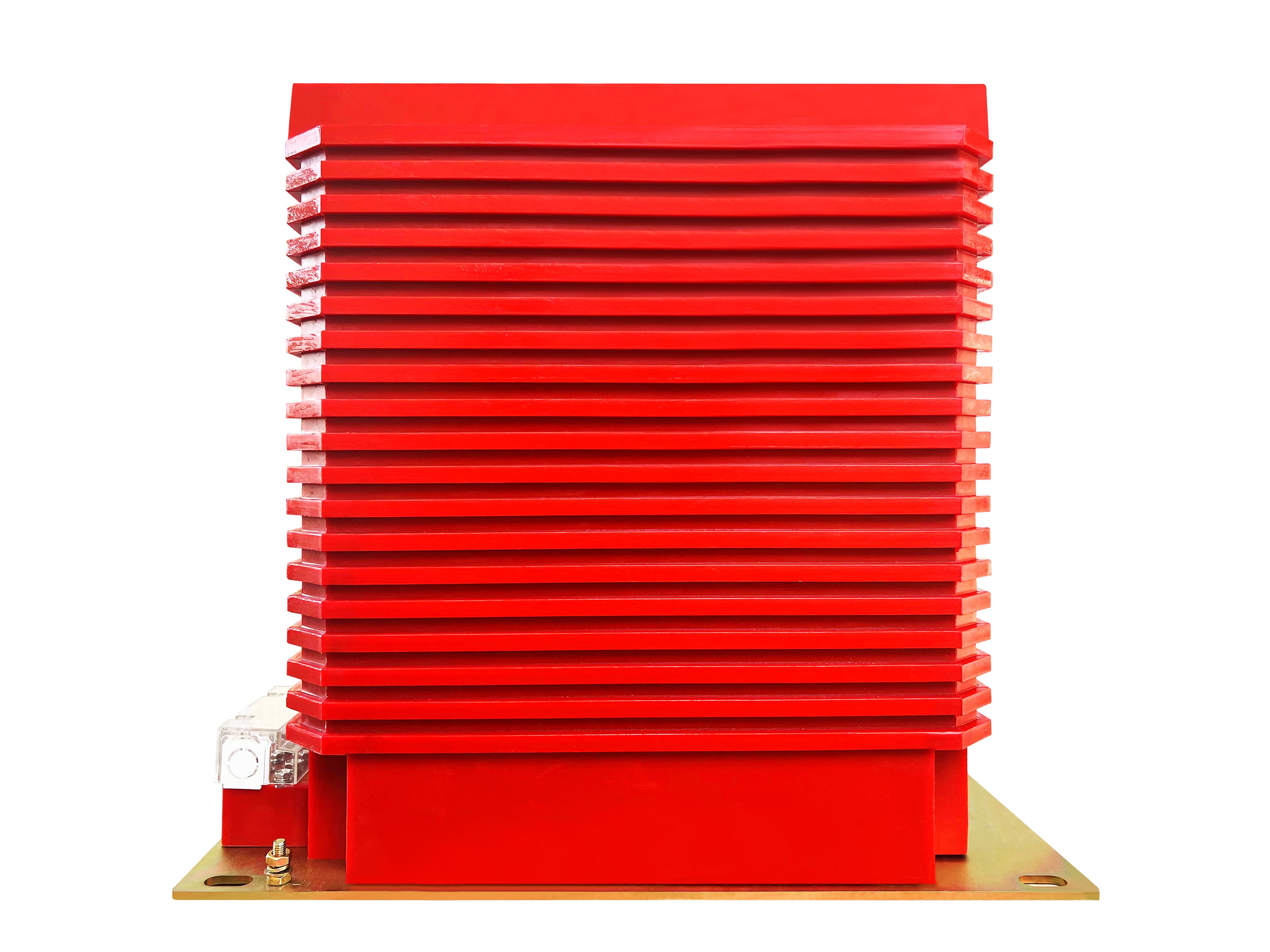
The current transformer range is built in the indoor and outdoor forms used in 12 kV and 40.5 kV distribution, with protection and metering cores available in the same window, so the two duties can be separated without changing the primary. Where the CT sits inside a distribution cabinet or feeds a metering box, the burden calculation above is the same calculation, with a different answer for every panel.
The purpose of the exercise is not precision for its own sake. It is to avoid the situation where the CT, the relay and the cable are each individually correct and the combination is not.
Frequently Asked Questions About CT Burden
What is CT burden?
Burden is the total impedance connected to the CT secondary, expressed as volt-amperes at rated secondary current. It is the sum of the relay and meter coils, the wiring resistance out to them and back, the terminals and the test block. If that total exceeds the rated burden of the CT, the CT saturates at a lower primary current than its datasheet implies.
How do you calculate the lead burden of a CT secondary?
Resistance equals resistivity times length divided by cross-section, and the length is the loop length, twice the one-way run. For copper, 0.0175 ohm square millimetre per metre at 20 degrees Celsius, rising to about 0.021 when the conductor is at 75 degrees. Lead burden in VA is that resistance multiplied by the square of the secondary current.
Should I use a 1 A or 5 A CT secondary for a long cable run?
For runs beyond roughly 50 to 100 metres, 1 A is usually the better choice, because lead burden falls with the square of the current. The same 200 metre loop that consumes 35 VA at 5 A consumes about 1.4 VA at 1 A. The price is four times the turns, a higher open-circuit voltage risk and relays that must be ordered for 1 A.
Does a higher accuracy class fix an over-burdened CT?
No. Class 0.5 or 0.2 defines the error at rated burden, and the CT cannot meet it beyond that burden. Moving to a higher class does not increase the VA it can drive. The real fixes are a larger secondary conductor, a shorter route, lower-burden devices or a CT with a higher rated burden and accuracy limit factor.
What happens if a CT secondary is left open circuit?
The current transformer behaves as a constant-current source, so with the secondary open the flux collapses and a very high voltage appears across the terminals, limited only by saturation. It is a hazard to people and to insulation. Never open a CT secondary under load, and use a test block that short-circuits the secondary before it disconnects the relay.
Published November 3, 2026 · Nahu Group (NAHU Electric Technology)