
A CT metering box is the enclosure that houses the current transformers, the test terminal block and the meter for a CT-operated metering point. Instead of forcing the full load current through the meter, the CTs step it down to a standard secondary level — usually 5 A or 1 A — and the meter measures that. The box exists to hold that arrangement in a fixed, sealable, inspectable form, so a utility can read a supply accurately and be confident the measurement has not been interfered with.
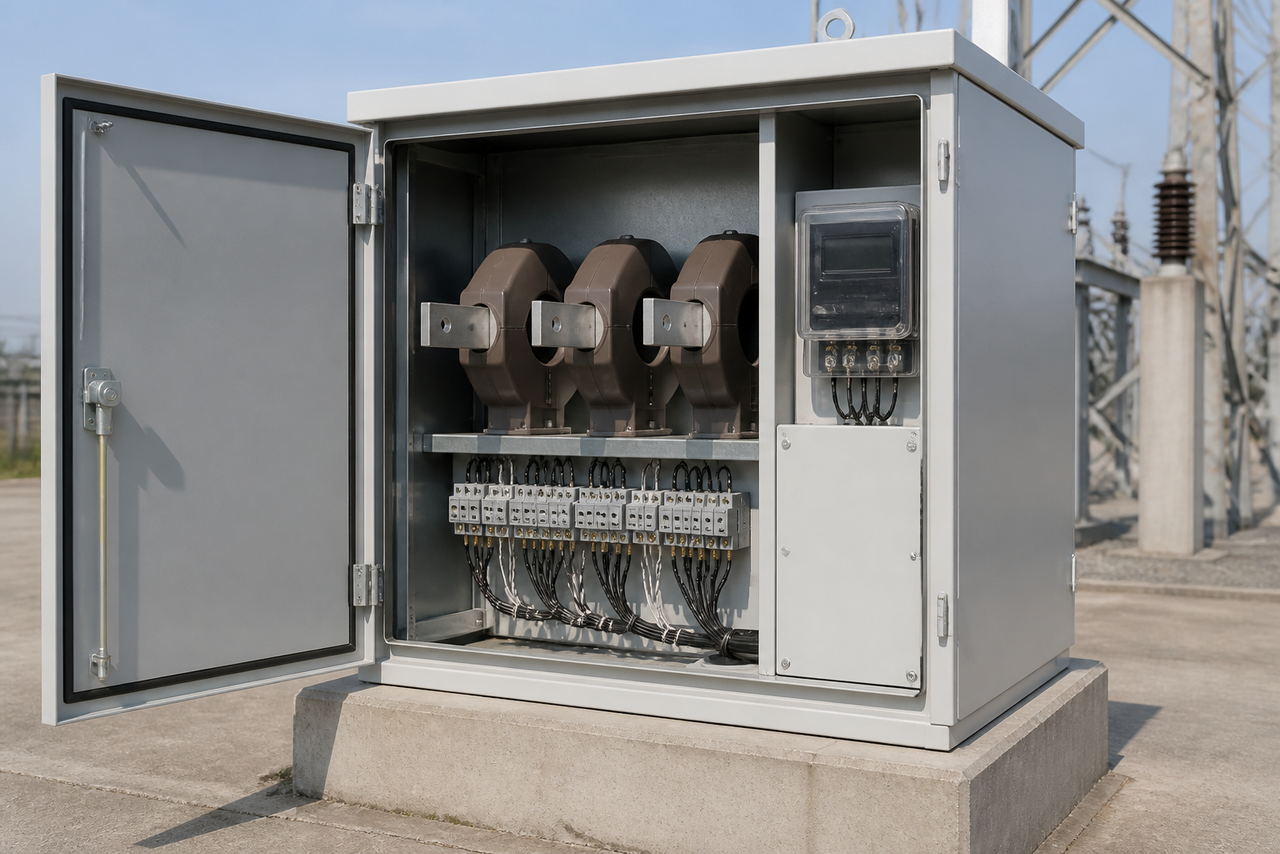
This guide is written for utility metering engineers, panel builders and contractors specifying metering equipment for commercial, industrial and distribution supplies. It covers what the enclosure contains, why CT-operated metering is chosen over a direct-connected meter, how the secondary wiring is arranged and earthed, and what a specification needs to state.
What is a CT meter box?
A CT metering box — written CT meter box in most enquiries, and called a CT metering cubicle, metering panel or CT chamber depending on the market — is a purpose-built enclosure installed at the point where a supply is measured. It contains the current transformers that scale the load current down, the test terminal block that lets an inspector verify the installation, and the meter itself. On larger supplies the same enclosure may also carry voltage transformers or a direct voltage connection for the metering circuit.
The key distinction is between direct-connected metering, where the full load current passes through the meter terminals, and CT-operated metering, where it does not. A CT metering box is the physical home of the second arrangement.
What does a CT metering box contain?
- Current transformers. Usually one per phase, sometimes a fourth on the neutral. Their ratio, accuracy class and burden are the numbers that decide whether the installation measures correctly.
- A test terminal block. A facility that lets a technician insert test or calibration equipment and short the CT secondary safely, without opening the secondary circuit under load.
- The meter. Mounted where it can be read and sealed, connected to the CT secondaries through the test block.
- Secondary wiring. Sized and routed so the CT burden stays within the CT's rated capability, with correct polarity throughout.
- Sealing points. Provision for utility seals on the meter, the test block and the enclosure itself.
- The enclosure. Indoor or outdoor, with the ingress protection and, where required, arc-rated construction that the location demands.
Why use CT-operated metering instead of a whole-current meter?
Direct-connected meters have a maximum rated current. Above it, the load cannot be passed through the meter at all — the terminals, the internal current path and the measurement accuracy will not support it. CT-operated metering removes that ceiling and brings three further advantages: the meter is smaller and cheaper for a given supply size, the heavy current path stays in the switchgear rather than being routed up to a meter position, and the metering equipment can be isolated for testing without interrupting the supply.
The trade-off is that accuracy now depends on the CTs as much as on the meter. A CT with the wrong accuracy class, an inadequate burden rating, or secondary wiring that is too long or too thin will distort the measurement no matter how good the meter is. That is why the CT specification, not the meter selection, is usually the part of a CT metering installation that needs the most attention.
| Whole-current (direct) metering | CT-operated metering | |
|---|---|---|
| Load current path | Passes through the meter | Passes through the CT primary; only the reduced secondary current reaches the meter |
| Practical current ceiling | Limited by the meter's rated direct current | Set by the CT ratio and the switchgear, not the meter |
| Where it is used | Domestic and small commercial supplies | Larger commercial, industrial and distribution supplies |
| Testing without outage | Difficult — the meter carries the load | Straightforward via the test terminal block |
| Accuracy depends on | The meter alone | The meter and the CTs, plus the secondary wiring burden |
How is the CT secondary wiring arranged?
Three-phase metering uses one CT per phase, with the secondaries connected in star so that the three phase currents sum correctly at the meter. Polarity is critical: the primary P1/P2 and secondary S1/S2 markings define the direction of measurement, and a reversed CT produces a metering error rather than an obvious fault, so polarity is verified before the installation is energised.
The secondary circuit is earthed at one point only. Earthing at a single designated terminal — commonly S1 or the terminal the manufacturer designates for the purpose — keeps the secondary at a defined potential without creating a parallel path that would divert current around the meter. Earthing the secondary at more than one point introduces circulating currents and corrupts the measurement.
The secondaries must also never be left open-circuited while primary current is flowing. An open secondary removes the counter-flux, and the CT behaves as a step-up transformer, developing a dangerously high voltage across its own terminals and risking insulation failure. The test terminal block exists precisely so that shorting is done deliberately, in a defined sequence, before any test lead is inserted.
Finally, the total burden matters. Every metre of secondary cable, every joint and every connected instrument adds impedance that the CT must drive. If the connected burden exceeds the CT's rated burden, the CT's accuracy class is no longer guaranteed. Keep secondary runs short, use adequate conductor cross-section, and state the connected burden in the specification.
Sealing and tamper evidence for revenue metering
For revenue metering, the enclosure is also a security device. Utility practice is to seal the meter, the test terminal block and the enclosure so that any intervention leaves visible evidence. That has three practical consequences for the specification: the enclosure needs deliberate provision for seals rather than holes added on site; the meter must be mounted so it can be read without breaking the meter seal; and access to the secondary wiring and the test block must be possible for authorised testing while remaining sealable afterwards.
Tamper detection also extends to the secondary circuit. If a CT secondary can be shorted or a phase bypassed without disturbing a seal, the measurement can be altered. Good design keeps the secondary circuit inside the sealed volume and brings only the test facilities to the sealed boundary.
How do you specify a CT metering box?
- Metering arrangement. Three-phase or single-phase, number of elements, and whether neutral current must also be measured.
- CT specification. Ratio, accuracy class for metering, rated burden, rated short-time withstand current, and the standard applied. Instrument transformers are standardised under the IEC 61869 series.
- Secondary current. 1 A or 5 A. This drives the meter type, the permissible cable length and the CT burden.
- Voltage circuit. Direct or via voltage transformers, and the connection point.
- Enclosure. Indoor or outdoor, ingress protection rating, material, mounting arrangement, and whether arc-rated construction is required.
- Sealing and access. Which parts must be sealable, and how authorised testing access is provided.
- Test facilities. Test terminal block type, shorting method, and any requirement for a dedicated calibration/test terminal.
- Documentation and approvals. Routine test certificates, wiring diagrams, and whatever local approval the utility requires.
How does a CT metering box differ from an HV metering box?
The distinction is what the metering circuit has to do. A CT metering box handles the current measurement side — stepping load current down to a meterable level — and is typically applied on low-voltage or secondary-side metering points. An HV metering box sits on the medium-voltage side of the network and must additionally handle high-voltage insulation, voltage transformation, and the safety and interlocking arrangements that go with direct connection to a 10-35 kV system.
In practice the two are often combined in one assembly on distribution networks, which is why specifications frequently blur them. For the medium-voltage side, see our guide to high-voltage metering boxes and the overseas utility metering box project. This article covers the CT enclosure itself.
Frequently asked questions about CT metering boxes
What is the difference between a CT metering box and a normal meter box?
A normal meter box holds a whole-current meter, so the full load current passes through the meter terminals. A CT metering box holds current transformers that reduce the load current to a standard secondary level, with the meter measuring that reduced current instead. The CT version is used where the supply is too large for a direct-connected meter.
Why can't a CT secondary be left open?
Because the CT then has nothing to oppose the primary flux and behaves as a step-up transformer, producing a very high voltage across its own secondary terminals. That endangers anyone nearby and can destroy the CT insulation. The secondary must be shorted before a test lead is inserted, which is exactly what the test terminal block is designed for.
Should the CT secondary be earthed?
Yes, and at one point only. Single-point earthing keeps the secondary circuit at a defined potential, while earthing at more than one point creates a parallel path that diverts current away from the meter and corrupts the measurement.
Does the CT accuracy class affect how much I am billed?
It affects how accurately the energy is measured, which is the same thing in practice. A CT whose accuracy class or burden rating does not suit the installation introduces a systematic error that applies to every reading. On a revenue metering point that error compounds continuously.
Where should the CT metering box be installed?
At or near the point of supply, so that the CT primary carries the full load being measured and the secondary run to the meter is as short as practical. Secondary run length directly affects burden, so keeping the box close to the metering position preserves accuracy.
Is 1 A or 5 A secondary better?
A 1 A secondary reduces I²R losses and the burden contribution of the wiring, which helps on long secondary runs. A 5 A secondary suits shorter runs and is the more common convention in many markets. The right answer depends on run length, the meter available and the CT burden rating — it is a system decision, not a universal one.
Why do utilities insist on seals?
Because revenue metering is evidence. Seals on the meter, test block and enclosure make unauthorised intervention detectable, and they protect the customer as much as the utility — a sealed installation is one where the reading can be trusted by both sides.
Metering equipment for distribution networks
Nahu Group manufactures current and voltage instrument transformers, metering boxes and medium-voltage distribution equipment for 10-35 kV networks, supplied to utilities, EPC contractors and panel builders. When you send a metering specification with the data listed above, our engineering team can return an offer that names the standard applied, the CT ratio and class, the secondary current, the enclosure rating and the documentation set. See the metering box range or our guides to specifying medium-voltage current transformers and choosing a current transformer ratio.
Sources and further reading
- IEC 61869-1:2023, Instrument transformers — Part 1: General requirements — IEC Webstore
- IEC 61869-2:2012, Instrument transformers — Part 2: Additional requirements for current transformers — IEC Webstore
- Installation guidance for current transformers, including single-point earthing of the secondary — Janitza knowledge base
- Electricity metering best practices, including revenue metering practice — Pacific Northwest National Laboratory