
An 11 kV cable termination kit is bought as a matched set — tube, stress control, sheds, lug, earth connection and sealing — sized to one cable construction, and most site failures trace back to a kit that did not match the cable rather than to a technology that did not work. So the first decision is not cold shrink or heat shrink. It is which cable the kit has to fit, and what the kit has to prove.
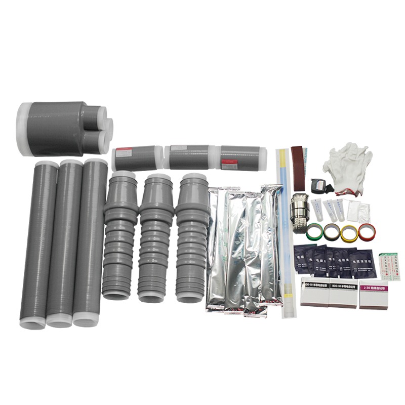
Terminations fail for three reasons: the field at the screen cut was not controlled, moisture reached the insulation, or the external surface was too short for the pollution it sits in. A kit is simply the packaged answer to those three problems, and it only works if the package was put together for the cable in front of the fitter. This article is written for the person who writes the bill of materials and the RFQ, not for the person holding the torch.
What an 11 kV Cable Termination Kit Has to Deliver
Four things, and every one of them has to be in the box: field control at the screen cut, a sealed insulation surface, an external profile with enough creepage for the site, and a conductor connection that matches the lug and the equipment terminal. A fifth item is documentary rather than physical — the installation instruction for that specific kit, in the language the crew reads, with the cable preparation dimensions drawn to scale.
The standard the cable side is judged against is IEC 60502-2, which covers 6 kV to 30 kV extruded-insulation cables: construction, dimensions and the test requirements the cable has to meet before an accessory is fitted to it. A kit that is correct for one cable to that standard can be wrong for another of the same voltage, because the standard fixes the insulation thickness and the screen construction, not the outside diameter tolerance the kit has to swallow.
"11 kV" Is a Nominal Name, Not a Cable Voltage Class
This is the single most common specification error in the Middle East and South Asia, and it is worth ten minutes before the enquiry goes out. "11 kV" describes the system. The cable is ordered by U0/U, and two different cables are used on 11 kV systems depending on how the neutral is earthed and how long an earth fault is allowed to persist:
| What the drawing says | Cable likely specified | Kit consequence |
|---|---|---|
| 11 kV, effectively earthed, cleared in seconds | 6/10 kV cable, Um 12 kV | 6/10 kV kit; wall thickness and stress-control diameter follow that cable |
| 11 kV, unearthed or impedance-earthed, long fault duration | 8.7/15 kV cable, Um 17.5 kV | 8.7/15 kV kit; a 6/10 kV kit will not have the insulation wall to match |
| 11 kV written with no earthing statement | Undetermined | The enquiry is incomplete — ask before quoting, not after delivery |
| 33 kV written, 11 kV intended | Copy-paste error in the schedule | Kit priced for the wrong class entirely |
The practical rule for the buyer: never accept "11 kV kit" as a description. Ask for the cable designation, U0/U, conductor size, conductor shape — stranded circular, sector-shaped or solid — insulation type, screen construction, and the outside diameter over insulation and over sheath. Those six values decide whether the kit fits, and none of them is visible from the system voltage.
What Changes From LV to MV, and What the Photo Shows
The principle is identical at 0.6/1 kV and at 11 kV: strip back in a fixed sequence, control the field, seal the surface, connect the conductor. What changes is the tolerance for error. On a low-voltage termination the insulation is thick relative to the voltage, so a slightly uneven cut costs little. At 11 kV the field at the screen cut is high enough that a few millimetres of the wrong profile becomes the failure point, which is why MV kits are supplied with a cutting template and LV kits often are not.
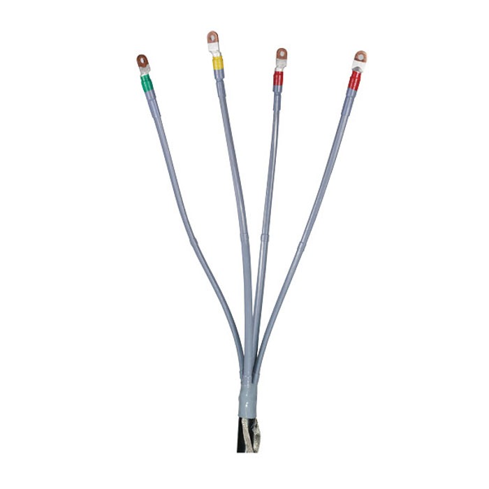
The four-core 0.6/1 kV termination above makes the point: four silicone tubes, four lugs, one earth connection at the gland, phase identification by colour. Nothing in that assembly is dimensionally critical to a millimetre. Scale the same construction up to 11 kV and every one of those steps acquires a number and a tolerance — the length of insulation exposed, the position of the stress cone relative to the screen cut, the length of screen left for the earth connection.
Inside the 11 kV Kit: The Bill of Materials to Check on Delivery
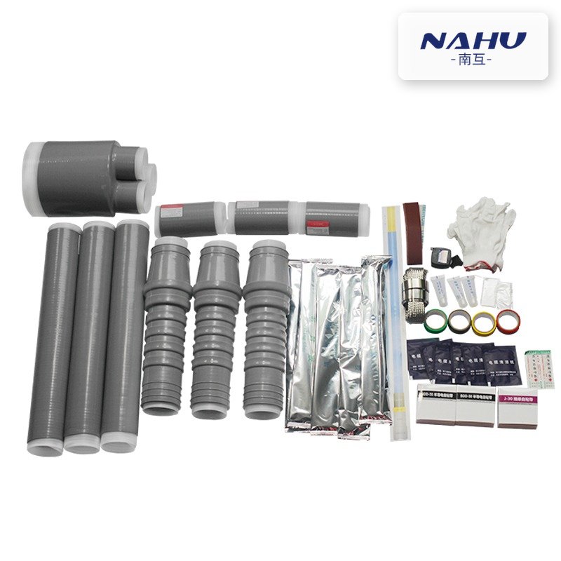
Open the box before it goes to site. A complete cold-shrink cable termination kit for one three-core termination normally contains the following, and a missing item is a stopped job rather than a small inconvenience:
| Item | What it does | What to check on delivery |
|---|---|---|
| Cold-shrink or heat-shrink tubes | Insulation reinstatement over the exposed core | Quantity matches core count; tube bore and length match the kit list |
| Stress-control element | Grades the field at the screen cut | Correct diameter range for this cable, not a universal part |
| Sheds or skirts | Extends creepage for outdoor service | Count matches the pollution level ordered; none supplied for indoor kits |
| Lugs or connectors | Conductor termination | Barrel size matches conductor class; palm drilling matches the equipment terminal |
| Earth connection kit | Bonds screen and armour to the earth bar | Constant-force spring or clamp sized to the sheath diameter; braid length sufficient |
| Sealing and filling materials | Blocks moisture paths at the sheath and the lug | Mastic and tape within shelf life; sealed sachets unopened |
| Preparation consumables | Cleaning, abrading, marking | Abrasive strip and cleaning solvent present; without them the crew improvises |
| Instruction sheet and template | Dimensions for this kit and this cable | Matches the kit part number on the label, in a language the crew reads |
Cold Shrink or Heat Shrink at 11 kV
Both technologies are in daily service at this voltage, and the choice is usually made on installer competence and site conditions rather than on electrical performance. Cold shrink removes the heat source, which matters inside a switchgear chamber, in a cable trench with limited access, or anywhere a hot-work permit is a problem. Heat shrink needs a controlled flame or hot-air gun and a fitter who can judge an even shrink; where that skill is available and repeatable, it is a proven and economical option.
The decision rule that survives contact with projects is simpler than a feature comparison: if the crew that will install the terminations has not done this specific kit before, choose the technology that removes the most variables from their hands. That is normally cold shrink, because the tube either fits the prepared cable or it does not, and the fitter's judgement is confined to the preparation dimensions. The side-by-side comparison of the two termination technologies covers the material behaviour in more detail; this article stays with the purchasing consequences.
Indoor or Outdoor: Sheds, Creepage and Pollution Level
The cable preparation is the same. The external profile is not. An outdoor termination carries sheds that break up water films and lengthen the surface path; an indoor termination is plain, because it lives in a compartment where rain and pollution are not the design case. Ordering an indoor kit for an outdoor position is a rework that shows up as tracking within a season or two.
| Site condition | Profile to specify | What the RFQ should say |
|---|---|---|
| Indoor metal-enclosed panel, clean atmosphere | Plain indoor termination | Indoor kit, state the compartment and the cable entry |
| Outdoor, light industrial or rural | Shedded outdoor termination | Outdoor kit with shed count stated |
| Coastal, desert with sand and dust, or heavy industrial | Shedded, extended creepage | State the pollution severity and the creepage distance required in mm/kV |
| Pole-mounted or overhead transition | Outdoor termination plus mechanical support | State the support arrangement and the cable drop |
Do not leave creepage to the supplier's default. Two kits of the same voltage and the same cable can differ in shed count and total creepage, and the difference is invisible until the site is coastal. Write the required creepage into the specification and require the offered drawing to show it.
Sizing the Kit to the Cable, Not to the Voltage
A cable termination kit is sized by diameter range, and the range is what fails when the cable is not the one assumed at enquiry stage. A kit covers, typically, a band of insulation diameters and a band of sheath diameters; a cable outside either band cannot be terminated correctly with it, no matter how carefully the fitter works. Three values decide it: diameter over insulation, diameter over sheath or armour, and conductor cross-section with its shape.
Single-core and three-core cables need different kits even at the same voltage and conductor size, because the shared insulated core in a three-core cable changes both the field distribution and the physical access. If the route is single-core, the formation and bonding scheme also has to be settled before the terminations are ordered, since the trefoil formation and sheath bonding arrangement determines what the termination has to withstand at its screen.
The Four Installation Faults That Cost a Second Kit
Every one of these is unrecoverable. Once a cold-shrink tube has relaxed onto the cable it cannot be repositioned, and a heat-shrink tube that has been over-shrunk cannot be recovered. The kit is consumed, the cable is shortened, and the joint or the panel has to wait for a replacement.
- Screen cut in the wrong place or with the wrong profile, so the stress-control element cannot sit where it was designed to sit
- Insulation surface contaminated or insufficiently abraded, leaving a conductive film under the tube that tracking follows later
- Tube installed before the earth connection was made off, forcing the fitter to cut it back to reach the screen
- Lug fitted after the tube rather than before, so the tube is damaged by the crimping operation
The commercial consequence is rarely the cost of the kit. It is the second mobilisation, the second permit, the cable shortened by a metre on a route that had no spare, and — where the termination is inside a panel — a second outage window. That is why the installation instruction is a procurement document and not a courtesy: a crew that has the drawing and the dimensions does not guess, and a crew that guesses consumes kits.
After installation the circuit is tested before energisation, and the test is specified by the project rather than by the accessory supplier. The VLF test voltage and duration practice for MV cables explains what the test proves and what it cannot: a withstand test finds gross defects, not a termination that will track in three years because its creepage was too short.
What the RFQ and Datasheet Must State
A cable termination kit enquiry that produces comparable quotations needs these lines, in this order. Anything missing comes back as an assumption, and assumptions are where the rework starts:
- Cable designation and U0/U, with the system voltage and the earthing arrangement stated separately
- Conductor material, cross-section and shape; insulation type; screen and armour construction
- Diameter over insulation, over metallic screen and over sheath, taken from the cable data sheet
- Core count and whether single-core or three-core, with the formation if single-core
- Indoor or outdoor, pollution severity, and the creepage distance required in mm/kV
- Technology preference, or an explicit statement that the supplier may offer either
- Lug type, palm drilling and material to match the equipment terminal, plus the earthing arrangement
- Quantity of terminations, spare kits required for the crew, and delivery schedule against the cable pull
- Documents: installation instruction, dimension drawing for approval, and the test certificate for the kit components
The same discipline applies to joints on the same route, and the joint kit specification checklist uses the same input values. Where a joint and a termination share a cable, order them together: a kit supplied months apart is a kit from a different production batch with a different instruction revision.
Where Nahu Group Fits
Nahu Group supplies cold-shrink cable accessories for 0.6/1 kV to 35 kV cables: indoor and outdoor terminations, joints and the associated kits. The models referred to here — NLS-35 indoor three-core and single-core, WLS indoor and outdoor types — are catalogue items in the cable accessories range. Kits are selected against the cable data sheet, and where a termination lands in a panel rather than a free-standing position, the switchgear cabinet configuration decides the cable entry and the space available for sheds. For branch or tee-off arrangements, the cable branch box range is the alternative to terminating three cables into one panel.
To get a configuration, send the cable data sheet with the diameters, the system voltage and earthing arrangement, indoor or outdoor position, pollution severity, conductor size and lug requirement, and the quantity per drum length. That is enough to select a kit and to issue a dimension drawing for approval before anything ships.
Frequently Asked Questions
Is a cable termination kit the same as a cable joint kit?
No. A termination brings a cable to an end at equipment; a joint connects two cable lengths. They use similar materials and similar field-control principles, but the dimensions, the number of interfaces and the mechanical requirements differ, and one kit cannot substitute for the other. Order by function, then by cable.
Can one kit serve both indoor and outdoor positions?
Only if the outdoor profile is supplied and accepted for indoor use, which wastes creepage and space in a compartment. Treat them as separate line items. In a project with both positions, ordering a single shedded kit for everything is how indoor compartments end up too tight for the cable box lids.
How long can a kit stay in store before it is used?
Silicone cold-shrink components have a defined storage life and must stay in their sealed packaging until the moment of use, because the elastomer relaxes and the surface can pick up contamination. Heat-shrink polyolefin is effectively inert in storage. Check the date on the label at goods-in and again before the crew opens the box.
Do I need a spare kit per site?
At least one per work location, and more where the crew is new to the kit. A termination that has to be redone cannot reuse a single component, and the cost of a spare kit is small against a second mobilisation to a remote pole or a substation that has already been handed over for energisation.
What test proves the termination is acceptable?
The after-installation voltage test named in the project specification, applied to the completed circuit at the stated voltage and duration. It detects gross installation defects and moisture. It does not prove creepage adequacy or long-term tracking resistance, which are settled by the kit selection and the pollution level written into the specification.
Sources and Further Reading
- IEC 60502-2:2014+AMD1:2024 — Power cables with extruded insulation and their accessories for rated voltages from 1 kV up to 30 kV, Part 2: Cables for rated voltages from 6 kV up to 30 kV — the cable construction, dimensions and test requirements that fix what the termination has to fit
- IEC 62271-200:2021 — High-voltage switchgear and controlgear, Part 200: AC metal-enclosed switchgear and controlgear for rated voltages above 1 kV and up to and including 52 kV — the cable compartment, entry and earthing provisions a termination has to work inside
- IEC 62271-1:2017 — High-voltage switchgear and controlgear, Part 1: Common specifications — the service conditions, including ambient temperature and pollution, that the assembly and its accessories are specified against
Published Nov 9, 2026 · Nahu Group (NAHU Electric Technology)