
VLF cable testing is an AC withstand test performed on shielded power cables at a frequency far below the operating frequency 鈥?usually 0.1 Hz rather than 50 or 60 Hz. The cable is energised at a defined test voltage for a defined time, and the test passes if it holds without breakdown. It replaced DC high-potential testing for medium-voltage cable maintenance because DC testing can leave charge trapped in insulation defects.
The appeal of the very low frequency is practical rather than theoretical. A cable is a large capacitor, and the current needed to charge it is proportional to frequency. Testing at 0.1 Hz instead of 50 or 60 Hz reduces the charging current by a factor of several hundred — Eland Cables puts the figure at 600 times less current and power — which is why a VLF set can be transported to a substation and connected to a cable that would otherwise need an impractically large test transformer.
This guide covers what the test proves, how IEEE 400.2 frames the voltage and duration, how the test is set up without damaging terminations, and what to specify when the cable accessories are ordered.
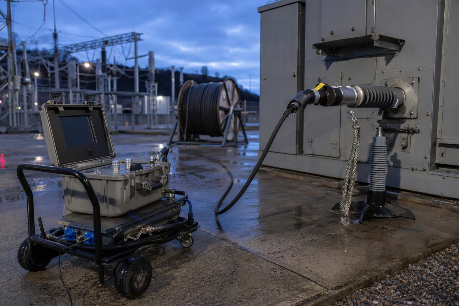
What Is VLF Cable Testing?
VLF stands for very low frequency. IEEE 400.2, the guide for field testing of shielded power cable systems using very low frequency, covers test methods that use AC signals at frequencies below 1 Hz. In practice the range runs from about 0.01 Hz to 1 Hz, and 0.1 Hz is the most commonly used commercially available frequency.
The output is still alternating current. It reverses polarity every half cycle, so the insulation sees an alternating stress rather than a unidirectional one. That distinction is the reason the method replaced DC testing: an AC stress distributes across the insulation by capacitance, as it does in service, while a DC stress distributes by resistance and can concentrate in voids.
Two waveforms dominate. A sinusoidal output produces a smooth wave whose r.m.s. value is 0.707 of its peak. A cosine-rectangular output produces a wave that reverses rapidly and holds, and for which the r.m.s. and peak values are assumed to be equal. Because the two waveforms relate peak and r.m.s. differently, a test voltage quoted without its waveform is ambiguous.
Cable manufacturers and standards bodies recognise the method across a wide voltage range. Eland Cables notes that VLF testing of solid dielectric cable is supported in IEC 60502 up to 35 kV and in IEEE 400.2 up to 69 kV.
Why Did VLF Replace DC Hipot Testing?
DC high-potential testing was the standard maintenance test for medium-voltage cable for decades, and it is still used for some acceptance work. Its weakness is what it leaves behind. A DC test polarises voids in the insulation; when the cable is returned to AC service, the trapped charge can contribute to failure. NETA World describes DC hipot as having been largely abandoned for maintenance testing for exactly this reason, and describes VLF as the method that does not polarise voids.
The second reason is diagnostic. A DC test produces a leakage current that decays as the dielectric absorbs charge, which makes interpretation dependent on the absorption behaviour of the insulation. A VLF test continuously charges and discharges the cable, so the measured current does not show the same absorption decay, and the same source can be used to run tan delta and partial discharge diagnostics.
The third reason is stress equivalence. A VLF test at an appropriate voltage is intended to reproduce, in a manageable test time, the kind of stress that would initiate failure in a defective cable in service. That is a different objective from measuring insulation resistance, and it is why VLF is described as a withstand test rather than a measurement.
What Test Voltage and Duration Does IEEE 400.2 Specify?
The guide does not reduce the question to a single number, because the answer depends on whether the test is an acceptance test on new cable or a maintenance test on aged cable, and on the waveform being used.
For acceptance testing, Eland Cables summarises the common practice as test voltages of 2.5 to 3 times the line-to-ground system voltage. HVI, reproducing IEEE 400.2 Table 3, describes the installation and acceptance levels as based on worldwide practice of from less than 2 U0 to 3 U0, where U0 is the rated r.m.s. phase-to-ground voltage, for cables rated between 5 kV and 69 kV. The maintenance level is about 75 percent of the acceptance level.
Duration is where reports most often diverge from the guide. HVI states that the recommended minimum testing time for an installation or acceptance withstand test on new cable circuits is 60 minutes at 0.1 Hz, and that a simple withstand test on aged cable circuits has a recommended minimum of 30 minutes. The guide also allows a test time within the range of 15 to 30 minutes where the monitored characteristic remains stable for at least 15 minutes and no failure occurs.
Those two statements are frequently read as contradictory, and NETA World makes the same observation. The practical resolution is procedural: decide in advance which duration the project will use, write it into the test procedure, and apply it consistently, so that results from different cable sets can be compared. A test that stops at 15 minutes on one feeder and 60 minutes on another is not a comparable data set.
| Typical voltage basis | Duration guidance | Purpose | |
|---|---|---|---|
| Acceptance, new cable | Approximately 2.5 to 3 U0, per IEEE 400.2 Table 3 practice | 60 minutes at 0.1 Hz | Prove installation and accessories before energisation |
| Maintenance, aged cable | About 75 percent of the acceptance level | 30 minutes at 0.1 Hz minimum | Detect severe degradation before it becomes a service failure |
| Shortened withstand | Same voltage basis | 15 to 30 minutes if the monitored characteristic is stable for at least 15 minutes | Practical compromise where the circuit cannot be held longer |
| VLF with tan delta | Stepped up to the withstand level | Follows the withstand profile | Trend dielectric losses and tip-up with voltage |
| VLF with partial discharge | Stepped up to the withstand level | Follows the withstand profile | Detect and locate discharge activity during the test |
Why Does the Test Setup Decide the Result?
A VLF test applies a voltage above the operating level to a cable end that was designed to be connected to something, not to stand in free air. That mismatch is the single most common cause of a cable being condemned when the cable is sound.
NETA World describes a case in which six conductors terminated with load-break elbows failed a DC hipot test. The elbows were hanging in free air with the test lead inserted into the load-break probe, and above roughly 30 kV DC the elbow flashed over to its semiconductive layer. The elbow was not designed with creepage distances for free-air energisation; it was designed to be plugged into an insulated stand-off or a bushing. The cable was not at fault; the test arrangement was.
The same logic applies at VLF. Load-break and dead-break terminations need insulated stand-off plugs, junction bars and, for dead-break systems, insulated plugs on the non-test end so that the cable system is properly isolated rather than left open in air. Cable shields must be grounded, including the wire connected to the eye of a load-break elbow. For standard live-front terminations, corona balls reduce air ionisation at the test end and improve both the withstand result and any tan delta reading taken at the same time.
None of this is exotic equipment, but it has to be planned. Test rods and adaptors for separable connectors can carry lead times, and a crew that arrives without them will improvise 鈥?which is how a passing cable becomes a failing one.
Is a VLF Test Non-Destructive?
Not unconditionally. VLF testing does not polarise voids the way DC testing does, which is the sense in which it is described as non-destructive. But a withstand test is designed to fail defects, and a cable with advanced degradation can break down during the test.
IEEE 400.2 addresses this directly. NETA World quotes section 5.1.2: if the accessory or cable insulation is in an advanced condition of degradation, the test can cause breakdown before it can be terminated when using test voltages above the operating voltage, and crews should be prepared to install a new splice, cable or termination if failure occurs during the test. A test procedure that does not plan for a failure is not a complete procedure.
The risk is concentrated at accessories. Joints, terminations and separable connectors are where installation quality varies most, and where water ingress and mechanical damage accumulate. That is also why the condition of those accessories should be established before the test, not discovered by it.
VLF Withstand, Tan Delta and Partial Discharge: What Is the Difference?
A plain VLF withstand test is pass or fail. The cable either holds the voltage for the duration or it does not, and there is no numeric criterion beyond the test set not tripping and the current remaining steady. That simplicity is its strength and its limit: it finds severe defects and says nothing about marginal ones.
Adding tan delta turns the same voltage source into a measurement. The dielectric loss angle is recorded as the voltage is stepped up, and the change between steps 鈥?the tip-up 鈥?indicates whether the insulation is behaving non-linearly. Adding partial discharge detection allows discharge activity to be seen and, with the right sensors, located.
Both diagnostics have practical limits on short cable runs. NETA World notes that on runs shorter than about 100 feet, and sometimes as short as 40 feet, the cable capacitance is so small that the leakage current is near the resolution of the test set, and leakage across the termination can dominate the tan delta reading. Humidity during the test can move the numbers further. A tan delta result on a very short run should therefore be treated as indicative rather than decisive.
What Does This Mean When You Specify Cable Accessories?
The test outcome depends on the accessories as much as on the cable, so the specification should make the accessories testable. Three requirements do most of the work.
- Terminations with adequate creepage and a defined test interface. A termination that cannot be energised in air without flashover forces the crew into improvised shielding, which is where false failures come from.
- Compatible separable connectors and stand-off accessories. If the design uses load-break elbows or dead-break T-bodies, the insulated plugs and test rods needed for the withstand test should be identified at the ordering stage, not at commissioning.
- Joint kits matched to the cable construction. A joint that is correct for the conductor size but wrong for the insulation type will pass a visual inspection and fail under test.
Nahu Group manufactures cable accessories, separable connectors and cable branch boxes alongside its instrument transformer and switchgear lines. For projects where the cable system is tested after installation, the accessory selection is part of the test plan. The cable joint kit guide covers what a kit should contain, the cold shrink versus heat shrink comparison explains termination selection, and the trefoil formation guide covers the layout that affects sheath voltage on single-core runs.
What Should Be in the Test Procedure?
A procedure that can be audited afterwards contains the following, in this order:
- Cable identification, length, voltage class and insulation type
- The standard and edition being followed, and the table or clause that supplied the voltage
- Test voltage expressed as a multiple of U0, with the waveform stated
- Duration, and the criterion for shortening it if the guide allows that
- The accessories fitted at both ends, and how they were insulated for the test
- Grounding arrangement for shields and for the non-test end
- Instrument calibration status and the record of the applied voltage
- The action plan if the cable fails 鈥?who authorises a splice, and what spare material is on site
The last item is the one most often missing. A test that is designed to find defects will occasionally find one, and the difference between a two-hour repair and a two-day outage is whether the joint kit and the splicer were planned for.
Frequently Asked Questions About VLF Cable Testing
What is VLF cable testing?
It is an AC withstand test on shielded power cable performed at a frequency below 1 Hz, usually 0.1 Hz. The cable is energised at a defined voltage for a defined time and passes if it holds without breakdown.
Why is 0.1 Hz used instead of 50 Hz?
A cable behaves as a large capacitor, and the current needed to charge it is proportional to frequency. Testing at 0.1 Hz reduces that current by a factor of several hundred, which makes the test set portable.
What test voltage does IEEE 400.2 recommend?
Acceptance levels are commonly expressed as 2.5 to 3 times the line-to-ground voltage, and IEEE 400.2 Table 3 practice spans from less than 2 U0 to 3 U0 for cables rated 5 kV to 69 kV. Maintenance levels are about 75 percent of the acceptance level.
How long should a VLF test last?
IEEE 400.2 gives 60 minutes at 0.1 Hz for installation and acceptance tests on new cable, and 30 minutes as the recommended minimum for a simple withstand test on aged cable. A shortened test of 15 to 30 minutes is allowed where the monitored characteristic stays stable.
Can VLF testing damage a cable?
It can fail a cable that is already severely degraded. IEEE 400.2 notes that testing above operating voltage can cause breakdown in insulation in an advanced condition of degradation, so crews should be prepared to replace a splice, cable or termination.
What is the difference between VLF withstand and VLF tan delta?
A withstand test is pass or fail: the cable holds the voltage or it does not. Tan delta uses the same voltage source to measure dielectric losses and how they change as voltage steps up, which gives an indication of insulation condition rather than a simple verdict.
Why do load-break elbows need special preparation for testing?
They are designed to be plugged into an insulated stand-off or bushing, not energised in free air. Without insulated stand-offs and proper shielding, the elbow can flash over at test voltage and be mistaken for a cable failure.
Is VLF testing required for new cable installations?
It is widely specified as an acceptance test because it checks installation work as well as cable, but the requirement comes from the project specification and the applicable standard, not from the cable alone. Confirm the voltage, duration and waveform before the test.
Sources and Further Reading
- HVI 鈥?VLF cable test voltages per IEEE 400.2 鈥?frequency range, waveforms, Table 3 voltage practice and test durations
- Eland Cables 鈥?VLF testing for MV cables 鈥?charging current advantage, IEC 60502 and IEEE 400.2 voltage coverage, acceptance voltage range
- NETA World, Summer 2024 鈥?medium-voltage cable testing and the importance of processes 鈥?test-end preparation, DC polarisation, IEEE 400.2 section 5.1.2 and short-run tan delta limits
Published October 19, 2026 · Nahu Group (NAHU Electric Technology)