
A voltage presence indicating system (VPIS) is a fixed indicator built into medium-voltage switchgear that shows whether the main circuit at that point is energised. It couples capacitively to each phase, compares the derived signal with earth, and drives lamps or a display on the panel front. It needs no external supply, no operator action and no maintenance beyond a self-test. What it gives the operator is a first, immediate check before a compartment is opened or an earthing switch is closed.
What it does not give is a measurement, or proof that a circuit is dead. Those two limits are the reason the standards behind these devices were rewritten, and they are the reason a specification that names only "voltage indicator" is incomplete.
This guide covers what the device shows, how it differs from a voltage detecting system, how the capacitive coupling works, where phase comparison fits, and what a buyer should write into a 10–35 kV switchgear specification.
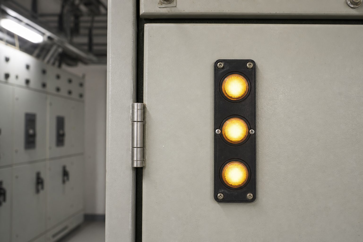
What Does a Voltage Presence Indicating System Actually Show?
The device shows the voltage condition of the main circuit it is connected to. In practice that means three indications, one per phase, each of which is either lit or not lit. The operator reads the set of three, not a number.
The distinction matters because the words "presence" and "absence" carry more weight than the display suggests. The scope of the current standard describes a voltage detecting and indicating system as a device used to detect and indicate the presence or absence of operating voltage, and then states plainly that it is not intended to distinguish between voltage not present, defined as below 10% of nominal voltage, and a dead circuit at zero volts. A dark lamp therefore means "no operating voltage detected at this point", not "this conductor is at earth potential".
Two practical consequences follow. First, the indicator is an operator aid during normal switching, not an isolation certificate. Second, a tender that asks for a "voltage indicator" without naming the standard, the coupling principle and the phase-comparison provision will usually receive three different products from three suppliers, each of which meets a different document.
VPIS, VDS and VDIS: What Is the Difference?
Three abbreviations appear in switchgear documents, and they are not interchangeable. Two of them describe older standards; the third is the document that replaced both.
| VPIS | VDS | VDIS | |
|---|---|---|---|
| Stands for | Voltage presence indicating system | Voltage detecting system | Voltage detecting and indicating system |
| Standard it came from | IEC 62271-206, first edition 2011 | IEC 61243-5, published 1997 | IEC 62271-213, published 2021 |
| Scope | Indicators incorporated in AC switchgear and controlgear covered by IEC 62271-200 or IEC 62271-201 | Single-pole systems capacitively coupled to live parts, 1 kV to 52 kV | Indoor and outdoor high-voltage equipment above 1 kV, service frequencies 16.7 Hz to 60 Hz |
| Status today | Superseded | Superseded | Current |
The 2021 document is not a cosmetic revision. It combines the content of the two earlier standards with changes in the technical and physical requirements, and it introduces the combined term. A specification written in 2026 that still cites IEC 61243-5 alone is asking for a device defined by a 1997 document, and a supplier quoting to that specification may be quoting an obsolete design.
There is a second, subtler carry-over. IEC 62271-206 stated that the indication of a VPIS alone is not sufficient to prove that the system is dead, and that where operating procedures make it mandatory, voltage detectors according to the IEC 61243 series should be used. That sentence survives in substance in current practice: the indicator tells you what it detects, and the isolation procedure still needs a detector and an earth.
How Does a Capacitive Indicator Work?
Almost every VPIS on a 10–35 kV panel is a capacitive divider. A metal electrode is built into the bushing, the insulating barrier or a dedicated sensor, and it forms a capacitor between the live conductor and the electrode. A second capacitance, inside the indicator or its connecting lead, completes the divider to earth. The voltage that appears across the second capacitor is a small, fixed fraction of the phase-to-earth voltage, and the indicator uses it to drive the lamp.
Because the divider ratios must match, the indicator and the coupling electrode are a pair. Manufacturers provide a selectable coupling value so that one indicator family can be matched to different bushings and sensors, and the setting is normally fixed at the factory or on site with a switch inside the unit. A mismatched pair produces an indication that is dim, late or absent, and no amount of lamp testing will reveal it.
Sensitivity classes matter here. Voltage detecting systems are offered in high-resistance and low-resistance variants, commonly written HR and LRM, and the class determines the current the device draws from the coupling point and the load it presents to the divider. It is a compatibility question between the indicator and the sensor, not a quality ranking.
The same coupling point carries more than a lamp signal. Because the electrode is a stable, repeatable window onto the phase voltage, test instruments can use the indicator's output as a sensing point: one partial-discharge survey accessory takes its signal from the existing VPIS and uses the phase relationship to keep measurements comparable at the same location from visit to visit. That is a useful second life for the device, and it also confirms the central point: the output is a phase-referenced signal, not a calibrated voltage reading.
What Is Phase Comparison Used For?
Phase comparison answers a different question from presence indication: not "is this side live?" but "are these two sides in phase with each other?"
The common cases are closing a ring, paralleling two feeders, and energising a cable that has been jointed or re-terminated. Before a ring is closed, the two ends must be on the same phase rotation and the same phase angle; otherwise the closing operation is a fault. Before a new cable is put into service, the phase identification made at the far end has to be confirmed at the near end.
Switchgear indicators support this by providing a phase-comparison facility: the device supplies a continuous electrical signal at a socket, and a comparator connected across two such sockets reports whether the two signals agree. The comparator is a separate instrument, and the older VPIS standard explicitly covered phase comparators designed for use with VPIS, which is a useful reminder that the comparator is part of the system and has to be compatible with it.
Two cautions are worth writing into a method statement. Phase comparison proves agreement between two specified points; it says nothing about a third point and nothing about absence of voltage. And the comparator must be rated and matched for the indicator family on the panel, because a comparator that expects a different signal level will give an answer that is confident and wrong.
Where Should a VPIS Be Fitted on MV Switchgear?
The device belongs wherever an operator has to make a decision about the voltage state of a circuit before acting. On a typical 11 kV or 33 kV panel that means:
- Each ring or cable way — on the cable side of the switching device, so the indication relates to the conductors that will be worked on
- The incoming or busbar section — so the state of the busbar can be confirmed before a section is earthed or extended
- Transformer feeders — where the cable or the fuse compartment is opened for maintenance
- Any compartment with an earthing switch — because the interlock logic assumes the operator has a means of checking voltage before earthing
The relationship with the earthing switch is the design point. On a gas-insulated secondary distribution panel, for example, the manufacturer states that the capacitive voltage detecting system is there to verify safe isolation from supply, and that the cable and fuse compartments are accessible only when the outgoing feeders are earthed. The indicator and the interlock are two halves of one procedure: the indicator tells the operator what the state is, and the interlock prevents the next step if the state is wrong.
On a single-line diagram, the indicator is usually drawn as a small set of three circles or a single block at the cable side of the way, and it is often omitted entirely because it is a secondary accessory. If the drawing does not show it, the specification still has to, or the panel may arrive without one. The ring main unit single line diagram guide covers where the metering and indication points normally sit.
What a VPIS Cannot Tell You
The limits are worth stating explicitly, because most of the field errors attributed to "the indicator" are actually errors of expectation.
- It does not measure voltage. There is no calibrated value to read, and no accuracy class in the metering sense
- It does not prove a circuit is dead. The standard itself separates "voltage not present" from a dead circuit; the isolation procedure still needs a detector and an earth
- It does not detect its own failed lamp unless it has a self-test, which is why the self-test is a specification item rather than a convenience
- It says nothing about phase sequence on its own; that requires comparison with a reference
- It is not a DC device, and its declared frequency range is part of the rating
- It is only as good as its coupling match. A correctly functioning indicator on a mismatched sensor is a silent failure
The last point connects to a wider commissioning habit: an indicator that reads "off" on a circuit that is known to be live is a fault report, not a finding. Proving the indicator works before relying on its silence is the whole purpose of the self-test.
How Do You Specify a Voltage Presence Indicating System?
A specification that can be quoted without argument states six things: the standard edition, the coupling arrangement, the indication and self-test requirements, the phase-comparison provision, the environmental rating, and the documentation.
| What to write | Why it matters | |
|---|---|---|
| Standard | The current edition of IEC 62271-213, with the year stated | Prevents supply against the superseded 61243-5 or 62271-206 documents |
| Coupling | Capacitive, one sensor per phase, matched to the bushing or sensor supplied with the panel | An unmatched divider gives late, dim or absent indication |
| Indication | One indication per phase, visible from the operating position, with a self-test that proves the lamp and circuit | Distinguishes a dead circuit from a dead lamp |
| Phase comparison | Provision for a comparator, with the comparator type or interface stated | Without it, phasing at commissioning needs a separate detector |
| Environment | Rated for the enclosure's indoor or outdoor condition, temperature range and UV exposure | Indicators fail at the lens and the label before they fail electrically |
| Documentation | Routine test record, wiring diagram, coupling value and replacement part number | Lets the owner replace a module without re-engineering the divider |
Two items are often left out and later regretted. The first is the coupling value: without it, a replacement indicator cannot be matched, and the panel owner is dependent on the original supplier for a part that should be interchangeable. The second is the phase-comparison interface: a comparator bought later may not fit the socket, and the alternative is a live-line phasing set and a longer outage.
Commissioning and Maintenance Checks
The checks are short, and they are all about proving the device before trusting it.
- Self-test with the panel de-energised. Confirm that the lamps and the test circuit respond as the manufacturer describes, and record the result
- Compare against a known live source. On first energisation, confirm that all three phases indicate, and that a phase known to be live reads live
- Check the phase relationship. Where the panel has comparison sockets, use the matching comparator to confirm phasing before a ring is closed or a cable is paralleled
- Re-check after bushing or barrier work. Any work that disturbs the coupling electrode or its lead invalidates the previous indication until it is re-proved
- Record the coupling value and part numbers. The next maintenance visit will need them
There is no routine calibration to schedule, because the device is not a measuring instrument. What does need attention is the physical condition of the lens, the label and the socket, and the integrity of the lead between the sensor and the indicator. On a coastal or dusty site those are the parts that degrade first, which is one reason the indicator's environmental rating belongs in the specification beside the enclosure's IP rating. The IP rating guide explains why an indoor panel is often IP4X rather than IP54, and what that means for accessories mounted through the door.
Frequently Asked Questions About Voltage Presence Indication
What is a voltage presence indicating system in simple terms?
It is the set of lamps on a medium-voltage panel that shows whether each phase of the main circuit is live. It works from a capacitive sensor, needs no battery or supply, and is there so an operator can see the state of the circuit before switching or opening a compartment.
Is a VPIS the same as a voltage detector?
No. A detector is a separate instrument used to prove absence of voltage as part of an isolation procedure. The indicator is a fixed operator aid. The standard for indicating systems states that the indication alone is not sufficient to prove that the system is dead.
What is the difference between VPIS and VDS?
VPIS came from IEC 62271-206 and covered indicators built into switchgear. VDS came from IEC 61243-5 and covered single-pole, capacitively coupled detecting systems from 1 kV to 52 kV. Both documents were replaced in 2021 by IEC 62271-213, which uses the combined term VDIS.
Does a dark lamp prove the circuit is dead?
No. The device indicates the presence or absence of operating voltage, and the standard explicitly says it is not intended to distinguish between voltage below 10% of nominal and a dead circuit. A failed lamp looks identical to a dead circuit unless the self-test is used.
How does a capacitive voltage indicator work?
An electrode in the bushing, barrier or sensor forms a capacitor to the live conductor. A second capacitor in the indicator completes a divider to earth, and the small voltage across it drives the lamp. The indicator and the sensor must be matched, which is why the coupling value is part of the design.
What is phase comparison on switchgear?
It is a check that two points are in phase before they are connected. A comparator is connected across the comparison sockets of two indicators and reports whether the signals agree. It is used before closing a ring or paralleling feeders, and it is not a substitute for proving the circuit dead.
Where should a VPIS be installed in a ring main unit?
On each way, at the cable side of the switching device, plus the busbar or incoming section where the busbar state matters. Any compartment with an earthing switch should also have a means of checking voltage, because the interlock assumes the operator can confirm the state before earthing.
Which standard applies to a VPIS today?
IEC 62271-213:2021 is the current document for voltage detecting and indicating systems. It replaced IEC 61243-5 and the first edition of IEC 62271-206. Project specifications should cite the current edition rather than either superseded standard.
Sources and Further Reading
- Orion EE — New Standard IEC 62271-213:2021 — the replacement of IEC 61243-5 and IEC 62271-206, and the scope wording of each document
- Genisys — Voltage Detecting System (VDS) — HR and LRM sensitivity variants, phase-comparison signal output and self-test
- Siemens — Switchgear Type 8DJH, catalog HA 40.2 (2022) — capacitive voltage detecting system for safe isolation, and IEC 62271-213 in the standards table
- EA Technology — VPIS accessory — using the VPIS output as a phase-referenced sensing point
The device is small with a narrow job, and the projects that get it wrong usually do so in the specification rather than in the product: an old standard edition, an unmatched coupling value, no self-test, no comparison sockets. Fix those four lines and the panel arrives with an indicator that can actually be relied on for the decision it was fitted to support.
Nahu Group builds ring main units, load break switches, earthing switches and metal-enclosed cabinets for 10–35 kV distribution, and works with the indicator and sensor arrangement shown on the project drawing. If a specification is still quoting IEC 61243-5, send it across and we will mark up what changes under the current document.
Published October 20, 2026 · Nahu Group (NAHU Electric Technology)