
A voltage transformer is accepted on evidence, not on a data sheet: the routine test record has to show ratio error, polarity, excitation behaviour and dielectric withstand for that individual unit. Everything else — the class printed on the nameplate, the ratio in the schedule, the burden assumed by the meter — is a claim until the record proves it. This is the document a utility reviewer asks for before energisation, and the one an EPC contractor forwards when a feeder trips on earth fault for no obvious reason.
The confusion usually comes from mixing two different things: what the factory must test on every unit, and what the standard only requires on a representative design. A type test report tells you the design is sound. A routine test record tells you the unit in the crate is the design you paid for. Buyers who accept the first in place of the second discover the difference at commissioning.

Which Tests Actually Decide Acceptance?
Four tests carry the acceptance decision for a voltage transformer. They are cheap, they are repeatable on site, and between them they catch almost every defect that survives packing and transport: wrong winding direction, a shorted turn, contaminated resin, moisture ingress, and a unit that was calibrated at a burden nobody will ever apply.
A fifth group — lightning impulse, temperature rise, short-circuit withstand, partial discharge — belongs to the design and is proven once by type test. Asking for those on every unit is not diligence, it is a misunderstanding of the standard, and a supplier quoting them per unit is either padding the price or testing something else.
The Four Tests a PT Record Has to Contain
The table below is the structure to require in the purchase order. The right-hand column is the practical reason each test exists, which is what decides whether a marginal result is acceptable.
| Test | What is measured | Routine on every unit | What it catches |
|---|---|---|---|
| Ratio and phase displacement | Secondary voltage against applied primary voltage, at 80%, 100% and 120% of rated voltage, at 25% and 100% of rated burden | Yes | Turn count errors, core defects, a unit that only meets its class at light burden |
| Polarity | Relative direction of primary and secondary windings | Yes | Reversed secondary, which silently inverts the residual circuit |
| Excitation characteristic | Secondary current against applied secondary voltage with the primary open | Yes | Shorted turns, core damage, mechanical damage in transit |
| Power-frequency withstand | Primary to earth and secondary to earth, one minute each | Yes | Resin voids, surface contamination, insufficient clearance |
| Impulse, temperature rise, short-circuit, partial discharge | Design limits | No — type test on a representative unit | Design weaknesses, not unit-to-unit variation |
If a supplier sends only a type test report, the missing document is the routine record. If they send a routine record with a single ratio reading, the missing content is the burden sweep — one point at rated burden does not show how the unit behaves at the 25% burden where a lightly loaded substation actually operates.
Ratio Test: Why Error and Phase Displacement Travel Together
The ratio test applies a known primary voltage and reads the secondary through a comparator or a calibrated burden. The result has two numbers, and both matter. Ratio error is the percentage deviation from the nominal ratio; phase displacement is the angle by which the secondary voltage leads or lags the primary, measured in minutes.
Metering classes limit both because a revenue meter multiplies voltage and current: an error in the voltage channel that looks small on its own compounds with the current channel error and with the power factor. Protection classes are looser on ratio and much looser on angle, because a distance or directional element only needs the voltage to be roughly right in magnitude and roughly in phase — but "roughly" has a limit, and a 3P unit that drifts past its composite error will move a protection boundary without anyone noticing.
Two practical points decide whether the record is worth reading. First, the readings must be taken at more than one burden, because the error of a voltage transformer depends on the load connected to its secondary. Second, the class on the nameplate only applies within a stated burden range — a 0.5 class unit at 30 VA is a 0.5 class unit; the same unit at 60 VA is not, and the meter will not tell you.
Polarity: The Test That Protects the Earth-Fault Scheme
Polarity is the cheapest test in the list and the one whose failure is most expensive to diagnose. Voltage transformers are normally supplied with subtractive polarity: at the instant the primary terminal is positive, the corresponding secondary terminal is also positive. The factory confirms it; the site electrician can destroy it by connecting the residual windings the wrong way round.
The consequence is specific. In a broken-delta residual connection, the three secondary windings are connected in series so that their voltages add to zero under balanced conditions. Reverse one unit and the sum is no longer zero — the relay sees a standing 3U0 on a healthy feeder. Earth-fault protection then either operates on a healthy circuit or is desensitised so far that a real fault is missed. Neither symptom points at the voltage transformer, which is why the fault is often found only after a switching operation is blamed on something else.
Test it at the terminal box, not at the transformer body, and record the terminal markings. The voltage transformer selection guide covers how the winding arrangement is chosen; polarity is simply the check that the arrangement arrived as drawn.
Excitation Test: What the Curve Proves About the Winding
The excitation test is done with the primary open and a variable voltage applied to the secondary. The result is a curve of secondary current against applied voltage, and its shape is the fingerprint of the magnetic circuit. A healthy unit follows the type-test curve closely; a unit with shorted turns draws more current at the same voltage, and the curve bends away from the reference well before the nameplate ratio looks wrong.
This is where voltage transformers and current transformers are often confused. A CT excitation test is done from the secondary with the primary open too, but the CT is a series device and its curve is read for the knee point that defines how much primary current it can transform before saturation. A PT is a parallel device: its curve is read for agreement with the reference, not for a knee that sets a protection limit.
Two cautions belong in any test procedure. The primary must be isolated and earthed before the test, because applying voltage to the secondary of a unit still connected to a live busbar back-feeds the primary at the ratio — a lethal mistake that has been made on more than one commissioning site. And the comparison must be against the curve for that model and ratio, not a generic shape, because saturation behaviour differs between a 10 kV unit and a 35 kV unit with a much larger core.
Power-Frequency Withstand: Voltage, Duration and What Counts as a Pass
The withstand test proves the insulation, and it is the test most often reduced to a formality. Applied voltage depends on the highest voltage for equipment, and the duration is one minute in the standard routine sequence. The commonly specified levels are 42 kV for 12 kV units, 65 kV for 24 kV and 95 kV for 36 kV, with the secondary winding tested separately at a low voltage such as 3 kV. Confirm the edition of the standard called in your specification before quoting these as acceptance values.
The judgement is not only "no breakdown". A unit that holds the voltage while its leakage current climbs steadily is on its way to failing, and a unit whose insulation resistance drops after the test has absorbed moisture. Record insulation resistance before and after, and treat a large drop as a fail even when nothing flashed over. For outdoor units stored on site before installation, this is the test that reveals a damaged gasket or a cracked shed.

Pass or Fail: The Criteria Worth Writing Into the Specification
A specification that says "routine tests according to IEC 61869-3" leaves the acceptance decision to the supplier's own interpretation. The clause below is what turns the test into a gate.
| Check | Acceptance condition | Where it fails in practice |
|---|---|---|
| Ratio error | Within the limits of the declared class at 80-120% rated voltage and 25-100% rated burden | Unit meets class at 25 VA, exceeds it at the 50 VA the meter actually draws |
| Phase displacement | Within the class limit in minutes at the same points | Ignored on protection cores, then a directional element mis-operates |
| Polarity | Subtractive, terminal markings matching the drawing | Residual circuit wired reversed during panel assembly |
| Excitation curve | Deviation from the type-test curve within the agreed tolerance, typically 10% | Shorted turn from transport impact, invisible on a single-point ratio check |
| Withstand | No breakdown, no significant leakage rise, insulation resistance unchanged after the test | Moisture ingress after months of outdoor storage |
The five failures that actually turn up at site acceptance follow the same pattern: somebody checked one point instead of the range. A reversed residual winding. A ratio that is correct but a burden that is exceeded. An excitation curve that shifted after a drop in the container. Insulation resistance that fell from four figures to two after a season in a coastal yard. And a ratio that does not match the meter multiplier, which surfaces months later as a billing dispute between the utility and its customer.
The same discipline applies to the current transformers on the same feeder, and the primary injection test procedure for current transformers covers the equivalent checks on that side. Where the two records disagree about the same feeder, the error is usually in the wiring, not in the devices.
What to Send With the RFQ
A voltage transformer quotation is only comparable if the enquiry fixes the parameters that change the price and the accuracy. State them as requirements, in this order:
- Ratings. Rated primary voltage and the system earthing arrangement, rated secondary voltage, number of secondary windings, and whether a residual winding is required.
- Class and burden. Accuracy class per winding with the burden in VA and its power factor, for metering and for protection separately.
- Rated voltage factor. 1.2 continuous for an effectively earthed system, or the higher factor needed where the unit must ride through an earth fault for a stated time.
- Insulation level and environment. Highest voltage for equipment, indoor or outdoor, pollution level and creepage distance, ambient and altitude.
- Documents. Routine test record per unit with the four tests above, type test report for the design, approval drawing, and the standard edition applied.
Add the test report format if your utility has one. A supplier who can fill it without renegotiating the scope is a supplier who tests routinely rather than on request.
Where Nahu Group Fits
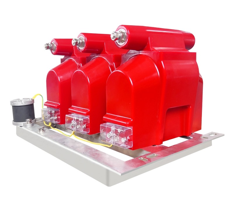
Nahu Group manufactures epoxy-cast voltage transformers for metering and protection on 11 kV, 33 kV and 35 kV networks — indoor units such as the JDZ and JDZX series, outdoor units such as the JDZW series, and three-phase assemblies for compact substations. Each unit is issued with a routine test record covering ratio and phase displacement, polarity, excitation and power-frequency withstand, and the design is supported by type test reports that can be submitted for approval before the order is released.
The useful input from a buyer is the single-line diagram with the metering and protection cores marked, the burden of each connected device, and the environment the unit will live in. With those three, the voltage transformer range can be matched to the class and the voltage factor rather than to a catalogue page. Where the metering point is a combined installation, the metering box range takes the same transformers and the same test records into a single enclosure, and the current transformer range provides the matching current channel so that both halves of the measurement are proved to the same standard.
None of this replaces the site test. It simply means that when the site test is done, the only question left is whether the wiring matches the drawing — not whether the device left the factory correct.
Frequently Asked Questions About PT Testing
What is the difference between a routine test and a type test on a voltage transformer?
A routine test is performed on every unit before delivery — ratio and phase displacement, polarity, excitation characteristic and power-frequency withstand. A type test is performed once on a representative design and covers impulse withstand, temperature rise, short-circuit withstand and partial discharge. The routine record proves the individual unit; the type report proves the design it came from.
What ratio error is acceptable for a 0.5 class PT?
Within the limits set by the standard edition in your specification, and only inside the declared burden range. The practical test is the burden sweep: the unit must stay inside its class at both 25% and 100% of rated burden, not only at the point where it was calibrated.
Why does PT polarity matter so much?
Because the residual or broken-delta connection adds three secondary voltages that should cancel. One reversed unit leaves a standing residual voltage on a healthy feeder, so earth-fault protection either mis-operates or is desensitised. The failure does not look like a transformer fault, which is why it takes so long to find.
Can a voltage transformer be tested on site?
Ratio, polarity and insulation resistance can be checked on site with portable equipment, and they should be, because transport and storage cause most of the damage that factory tests cannot catch. The excitation comparison is better done against the factory curve, and the power-frequency withstand belongs in a workshop rather than on a live installation.
What is the rated voltage factor and why does 1.9 appear in specifications?
The voltage factor states how much above rated voltage the transformer must remain accurate and thermally safe. A factor of 1.2 continuous suits an effectively earthed system; a higher factor such as 1.9 for a limited time is specified where the unit has to ride through an earth fault on an isolated or resonant-earthed network. It changes the design and the price, so it belongs in the enquiry, not in a footnote.
Does a passing factory test mean the metering will be accurate?
Only if the burden connected at site is inside the range the unit was tested at, and only if the ratio matches the meter multiplier. Both conditions fail more often than the transformer does — which is why the burden sweep and the ratio in the metering schedule deserve as much attention as the test certificate itself.
Published Nov 3, 2026 · Nahu Group (NAHU Electric Technology)