
Multiply the current transformer ratio by the voltage transformer ratio and you have the meter multiplier: a 100/5 A CT with a 10 000/100 V VT gives 20 × 100 = 2000, so 1 kWh on the meter is 2000 kWh on the invoice. Get either ratio wrong and the installation still reads, still logs, and is wrong by the same factor every month. That is why the ratio pair belongs on the approved drawing and on the box nameplate, not in a commissioning engineer's notebook.
How the Ratio Chain Sits Inside a V/V Metering Box
An outdoor high-voltage metering box measures a three-phase circuit with two current transformers and two voltage transformers connected V/V. Two elements are sufficient because of Blondel's theorem: on a three-wire system, n−1 measuring elements give total power whether the load is balanced or not. The box reduces primary current to 5 A or 1 A and primary voltage to 100 V, and the meter multiplies back.
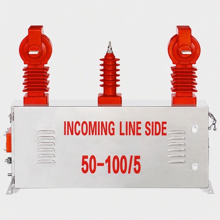
Everything downstream of that inherits both ratios: the meter constant, the billing system, the check meter and the loss calculation. A box is therefore specified as a ratio pair, not as two independent accessories, and the pair has to be repeated on the drawing, the nameplate and the test report.
Choosing the CT Ratio From the Load
Size the CT primary so that normal load sits between 50% and 80% of the rating. Below that band the core runs far from its calibrated range and the error grows; above it there is no headroom for overload, and the next size up is cheaper than a replacement.
A feeder that peaks at 320 A and normally runs at 250 A takes a 400/5 CT: 62% of rating at normal load, 80% at peak. The multiplier that follows is 80 × 100 = 8000 on a 10 kV system. The primary-selection arithmetic is the same one used for a standalone core, set out in how to choose a current transformer ratio.
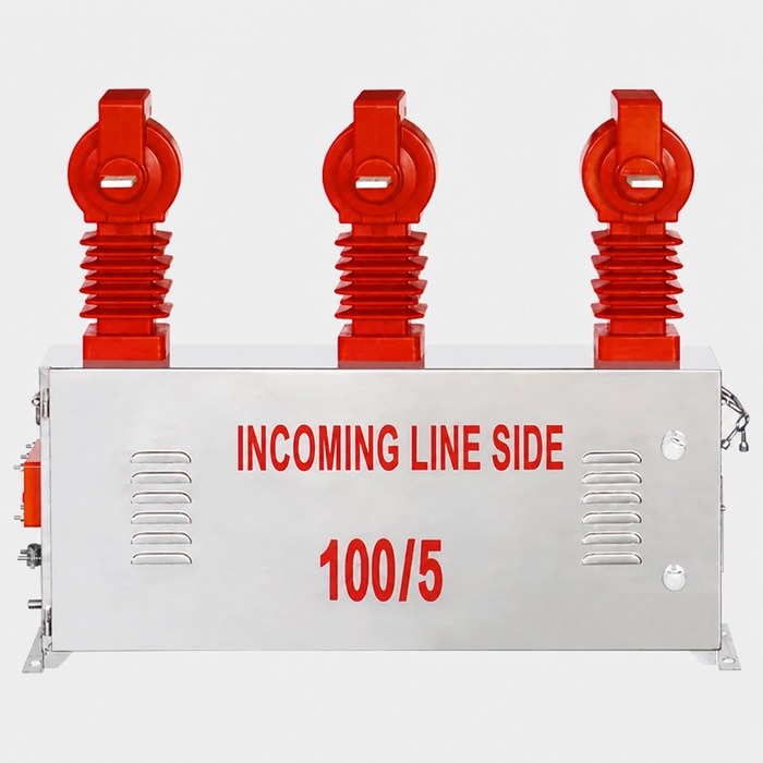
Dual-ratio cores are common on utility boxes, and the marking tells you both ranges: a core marked 50-100/5 gives 50/5 in series and 100/5 in parallel. Specify which connection is wired, record the multiplier for that connection, and treat the second ratio as a future option rather than a spare. Changing the link without changing the billing multiplier produces exactly the error the dual ratio was meant to avoid.
Choosing the VT Ratio
The VT ratio follows system voltage, not load: 10 000/100 V for a 10 kV system, 35 000/100 V for 35 kV. In a V/V connection the two transformers measure line-to-line voltage, so the ratio is the line voltage over 100 V. There is no sizing judgement here, only a check that the ratio matches the system the utility actually operates.
Two mistakes recur. The first is ordering on nominal voltage when the network runs above it: a feeder held at 10.5 kV against a 10 000/100 V ratio reads 5% high, and no multiplier corrects a ratio error. The second is mixing secondary voltages inside one box, for example a 100 V metering winding beside a 110 V auxiliary winding, which leaves the meter scaling one quantity and not the other.
The Ratio Table to Copy Into the Specification
Multiplier = CT ratio × VT ratio. Read the table across, then check the CT against the actual load profile before it goes into the datasheet.
| System | VT ratio | CT ratio | Multiplier | Typical use |
|---|---|---|---|---|
| 10 kV | 10000/100 V | 50/5 A | 1000 | Small industrial take-off |
| 10 kV | 10000/100 V | 100/5 A | 2000 | Distribution feeder, light load |
| 10 kV | 10000/100 V | 200/5 A | 4000 | Feeder up to about 200 A |
| 10 kV | 10000/100 V | 400/5 A | 8000 | Feeder to 400 A |
| 10 kV | 10000/100 V | 100/1 A | 10000 | Long secondary run, 1 A meter |
| 35 kV | 35000/100 V | 50/5 A | 3500 | 35 kV class box, light load |
| 35 kV | 35000/100 V | 200/5 A | 14000 | 35 kV class box, feeder load |
A 1 A secondary multiplies the figure by five against the same primary rating, which is one reason a replacement meter with the wrong secondary type over-reads or under-reads by exactly that factor.
Accuracy Class Limits Which Ratio You Can Use
Class 0.2S and 0.5S current transformers hold their accuracy from 1% to 120% of rated current; class 0.2 and 0.5 are specified from 5% upward. On a feeder that runs light at night, the S class is the difference between metering the night load and losing it inside the tolerance band. For revenue metering, specify an S class and then size the ratio so the light-load end is still inside the 1% floor.
Where Ratio Configuration Goes Wrong
- Oversized CT. A 600/5 CT on a feeder running 80 A sits at 13% of rating, where the error is largest and the multiplier of 12 000 magnifies it. The utility disputes the reading, and the correction is a new core, not a new meter.
- Wrong VT ratio. Every kWh on the feeder is scaled by the same wrong factor. It is usually found in an annual audit, a year of back-billing later.
- 5 A meter on a 1 A secondary. The reading is out by a factor of five and looks like a metering fault rather than a specification fault.
- Reversed polarity on one CT. One element subtracts instead of adds, so the meter under-reads badly at light load and almost correctly at heavy load, which defeats most fault-finding.
- Protection core used for billing. A 5P10 core is an accuracy-limit specification, not a metering class, and the utility will reject the installation at witness testing.
- Multiplier missing from the records. The next crew cannot verify the box without a primary injection test, and a simple meter swap turns into a site visit.
What to Put in the RFQ
The metering box range is configured to order, so the RFQ has to carry the ratio decisions rather than leave them to the supplier.
- System voltage and highest system voltage, with the operating range the utility actually holds.
- CT ratio, or both ratios where a dual-ratio core is wanted, and which connection is to be wired.
- VT ratio, and confirmation that the metering is V/V three-wire.
- Accuracy class and burden in VA for each core: for example 0.2S/10P10 with the burden per core stated.
- Secondary current, 5 A or 1 A, for CTs and for the meter.
- Enclosure, IP rating, meter compartment, observation window and sealing arrangement for tamper evidence.
- Documents: outline drawing for approval, ratio and polarity routine test report, and a nameplate showing the multiplier.
Where the metering point is a separate CT-operated box rather than a combined unit, the same ratio decisions apply and the CT meter box guide covers the enclosure and sealing requirements that go with them.
Where Nahu Group Fits
Nahu Group builds JLS-series outdoor metering boxes for 10–35 kV revenue metering, including the JLSGWV-10 and JLSZV-10. The 10 kV models combine two CTs and two VTs in V/V inside a stainless-steel enclosure with accuracy combinations such as 0.2S/10P10, an armoured secondary cable and an observation window for the meters.
Send the system voltage, the load profile in amps through the day, the accuracy class and burden you must meet, and the secondary current. We will return a ratio configuration with its multiplier, the enclosure drawing for approval, and the routine test data for the cores you select. For the measurement side of the same decision, the metering box guide covers construction and installation.
Frequently Asked Questions About Ratio Configuration
How do I calculate the multiplier of a metering box?
Divide the CT primary rating by its secondary, divide the VT primary by its secondary, and multiply the two results. A 200/5 CT gives 40 and a 10 000/100 V VT gives 100, so the multiplier is 4000. Confirm it against the nameplate before the meter is commissioned, and record it with the meter serial number.
What CT ratio should I choose for a 10 kV feeder?
Match the primary rating to the load so normal current falls between 50% and 80% of it. A feeder normally at 250 A with peaks near 320 A takes a 400/5 CT. Choosing one size up for future load is reasonable; choosing two sizes up is what produces the light-load error that shows up as unbilled energy.
Can the CT ratio be changed later without changing the meter?
Yes, if the meter is a standard secondary-input type: the meter sees 5 A or 1 A either way and only the multiplier changes. The mandatory step is updating the billing multiplier and the nameplate at the same time. A new core with an old multiplier in the billing system is a silent error until the next audit.
Why does the meter read five times too high or too low?
The usual cause is a secondary current mismatch: a 1 A secondary circuit connected to a 5 A meter input, or the reverse, scales every reading by five. Check the CT secondary rating against the meter input before suspecting the ratio, the multiplier or the meter itself, because the wiring is easier to verify and cheaper to correct.
Does a dual-ratio CT need two multipliers?
Yes. Each connection has its own multiplier, for example 1000 for 50/5 and 2000 for 100/5 on the same 10 kV box. Only the multiplier of the connection actually wired applies. Record both on the drawing, mark the wired one on the nameplate, and make the change procedure part of the commissioning file.
Published Nov 4, 2026 · Nahu Group (NAHU Electric Technology)