
When a feeder trips on a phase-to-phase short circuit, locating it is mostly arithmetic: the protection operated, the indicator at the mid-point flagged, and the patrol starts between the last two points that disagree. A single-phase earth fault is a different problem. The current is small, the feeder may stay in service, and nothing about the event is visible from the substation. This is where a fault indicator earns its place on the pole, provided its earth fault judgement is set as carefully as its short circuit judgement.
Why a Single-Phase Earth Fault Behaves Differently
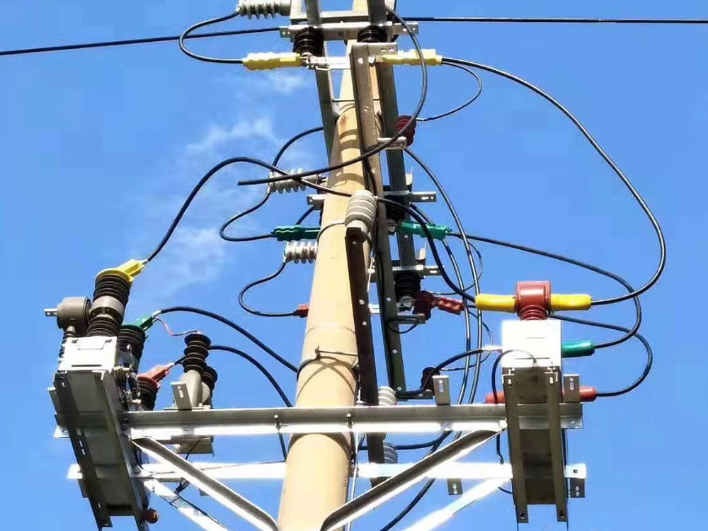
The physics depend on how the network neutral is handled. In an effectively earthed network an earth fault drives hundreds or thousands of amps, the protection clears it, and the indicator simply records which section lost voltage. In the isolated or resonant earthed medium-voltage networks that cover much of rural distribution, the fault current is limited to the network's capacitive charging current — often a few tens of amps or less. The feeder keeps running and customers notice nothing, but the faulted section keeps arcing quietly and will eventually become a two-phase fault.
That small, sustained current is what the earth fault channel has to catch, and it does not flow where the phase overcurrent channel is looking. It returns through earth and the capacitance of the healthy phases, so a device measuring only phase current sees almost nothing.
What the Indicator Actually Measures

A two-channel overhead indicator judges two separate questions. The short circuit channel watches phase current against a pickup above full load. The earth fault channel watches residual current: the vector sum of the three phase currents, measured either by a core balance sensor wound around all three conductors or by summing three phase sensors. On a healthy feeder that sum is near zero, whatever the load. On the faulted section it equals the earth fault current, continuously, for as long as the fault lasts.
The criterion is two-part: residual current above a threshold, sustained long enough to separate a fault from a transient. Directional models add a third input — they compare residual current phase against residual voltage to decide which side of the mounting point the fault lies on, which is what makes them usable on closed rings and parallel feeders.
How Flags Turn into a Location
Indicators are mounted at the sectionalizing points along the feeder, and after the event the patrol starts where the flags stop. The recloser tripped and reclosed; the indicators that saw the fault flagged and hold; the first unflagged indicator downstream marks the far edge of the faulted section. On a radial feeder with four sectionalizing points that turns an hour-long patrol into a two-span walk.
Reset behaviour matters more than most buyers expect. The flag must survive the reclose dead time, or the evidence disappears before the operator reads it. Timer reset longer than the dead time, restored-voltage auto-reset for feeders that stay in service after an earth fault, and manual reset for patrol-driven working all exist; a default reset shorter than the switching sequence it is supposed to describe does not.
The Main Causes of False Alarms
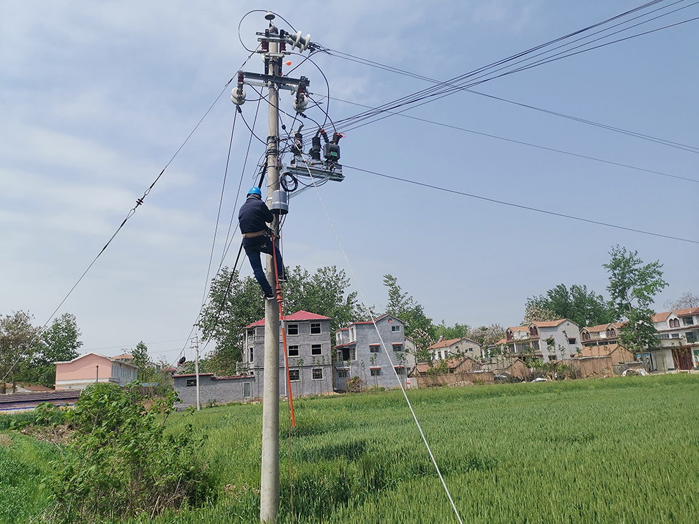
False alarms destroy trust in a device faster than missed faults, and they nearly always trace back to one of six causes:
- Threshold set below the standing residual. Every feeder carries some permanent imbalance that sums to a small residual current. If the earth fault pickup sits under that value, the indicator flags on an ordinary Tuesday.
- Transformer inrush. Energising a distribution transformer draws a magnetising surge that can produce a residual spike. Immunity logic keyed to the surge waveform is the fix; a bare magnitude threshold is not.
- Large motor starting. The starting current of a big motor shifts the residual momentarily on feeders with unbalanced single-phase loading.
- Lightning and induced surges. A nearby strike couples a fast transient into the loop. Duration criteria — the flag must persist several cycles — reject most of these.
- Sensor mounting faults. A split-core head not fully closed, or clamped past a junction where a spur taps off, changes what the sensor sums and manufactures a standing residual.
- Capacitor bank switching. The inrush of a stepped bank appears as a short residual transient that a well-set duration criterion rides through.
How to Set and Prove the Threshold
The defensible procedure takes three measurements. First, the standing residual current at peak unbalance, on the same sensor type that will be mounted. Second, the minimum earth fault contribution — on an isolated neutral this is bounded by the total capacitive charging current, which the utility can calculate or measure at the neutral. The pickup goes between the two numbers, conventionally at least twice the standing residual and comfortably below the minimum fault current. Third, a primary injection through the sensor head proves the mounted device flags, resets and communicates as the settings sheet says.
Settings belong in the handover file together with the standing residual measurement, because they are the reference for every later complaint about a flag that should not have been there.
| Event on the feeder | Phase channel | Earth fault channel | Correct response |
|---|---|---|---|
| Phase-to-phase short circuit | Flags | May flag | Feeder trips; locate by flag boundary |
| High-impedance earth fault, isolated neutral | Quiet | Flags if threshold is set low enough | Patrol the flagged section; feeder stays in service |
| Transformer energisation | May spike | May spike briefly | Immunity and duration logic reject; no flag held |
| Standing load imbalance | Normal load reading | Below threshold | No flag; this is the number the threshold is set against |
Where Nahu Group Fits
Nahu Group builds overhead line and cable fault indicators as a separate product family, including combined ground and short-circuit two-in-one units for overhead feeders and panel type indicators for switchgear, alongside the current transformers that feed directional schemes. Every model ships with the earth fault channel set against the buyer's network data — earthing arrangement, standing residual, sectionalizing plan — and commissioning support that includes the primary injection above.
Frequently Asked Questions About Fault Indicators
Can one fault indicator detect both short circuits and earth faults?
Yes, and on distribution feeders it should. A combined ground and short-circuit indicator carries two judgement channels: phase overcurrent for short circuits and residual current for earth faults. A single-channel overcurrent indicator cannot see a high-impedance earth fault at all, because the fault current never raises phase current above load.
Why did the indicator flag when there was no fault on the line?
In most cases the threshold sits below the feeder's standing residual current. Every real feeder runs with some imbalance, and that imbalance sums to a residual value the core balance sensor sees continuously. Measure it at peak unbalance, set the threshold at least twice that value, and most phantom flags disappear. The remainder usually comes from a split-core head that is not fully closed.
Do earth fault indicators work in compensated networks with a Petersen coil?
They work, but the logic changes. In a resonant earthed network the coil deliberately cancels the residual fault current, so magnitude alone is almost zero. Directional logic is required: the indicator compares residual current phase against a residual voltage reference and flags on the characteristic leading direction.
How is an overhead line fault indicator powered?
By the line itself. The sensing head clamps around the conductor and harvests energy from the load current, backed by a lithium cell for the periods when the feeder is de-energised and flags must be held. Panel and cable indicators take an auxiliary supply or a long-life battery, because the currents they measure cannot support harvesting.
Sources and Further Reading
- IEC 61869-1:2023 — Instrument transformers, Part 1: General requirements — the family standard behind the sensing heads and core balance sensors that feed the residual current channel.
- IEC 61869-2:2012 — Instrument transformers, Part 2: Additional requirements for current transformers — accuracy classes and errors for the phase and zero-sequence sensing on which the earth fault judgement depends.
- EEP — Using core balance current transformers for earth fault protection — how residual sensing works in practice, and why the standing residual sets the floor for any earth fault pickup.
Published Nov 6, 2026 · Nahu Group (NAHU Electric Technology)