
A cable joint kit fails inspection for one of six reasons, and none of them is the purchase price: the kit was sized to the conductor instead of the insulation diameter, the screen cut-back was done by eye, moisture or a void was trapped inside, the connector was crimped with the wrong die, armour continuity was never bonded, or the joint was backfilled before it was tested. Each leaves a signature a commissioning engineer can read, and each can be designed out of the job by a clause written before the kit is ordered.
Which cable joint kit mistakes actually fail an inspection?
The failures that reach commissioning are dimensional and procedural, not cosmetic. A joint that looks neat can still be rejected on a partial-discharge reading or a missing continuity record, because the defect that matters sits under the sleeve where nobody can see it afterwards. Every check below is therefore taken before the joint is closed or backfilled. The six failures normally surface in this order, so the table is written to be carried to the joint bay.
| Failure | What it looks like on site | Acceptance check before closing |
|---|---|---|
| 1. Kit sized to conductor, not insulation | Sleeve will not slide over the insulation, or sits loose with a gap at the shed root | Measure insulation diameter at three points and compare with the kit's stated range |
| 2. Screen cut-back by eye | Uneven pencil, nicked insulation, stress cone not seated on the insulation | Pencil length and diameter checked against the drawing; insulation clean under a light |
| 3. Moisture or a void trapped inside | Filler applied over a damp surface, or a bubble under the sleeve that will not flatten | Cable dried and cleaned before assembly; sleeve released from the center outward |
| 4. Wrong die or wrong compression | Loose strand in the crimp, connector rotated after crimping, barrel too short for the lug | Die marking matches the connector catalogue; required number of crimps per barrel |
| 5. Armour and screen left unbonded | Continuity end to end reads open, or braid fitted without a ferrule under the clamp | Continuity across the joint recorded, with bonding parts listed by name |
| 6. Backfilled before testing | Trench closed, then the sheath test fails and the joint has to be dug out | Test sheet signed before the backfill permit is issued |
Sizing the kit to the insulation diameter, not the conductor
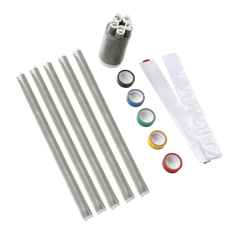
The dimension that decides whether a cold-shrink or pre-moulded kit fits is the diameter over the cable insulation, and for screened cable also the diameter over the screen. Conductor cross-section only indexes the catalogue. Two 240 mm² cables from different makers routinely differ by several millimetres over the insulation, which is wider than the tolerance of a pre-moulded joint body.
A kit range quoted as one cross-section is a warning sign. A workable kit is quoted as a band of insulation diameters with a matching band of connector barrels, and the intermediate joint page for 0.6/1 kV three-core cable shows the pattern: the size number steps with the cross-section from 10 mm² up to 400 mm², and each step carries its own insulation diameter band and joint weight. Ask for that band and put both numbers on the inquiry.
The connector follows the same rule. A compression lug is selected by barrel bore and by the die that matches it, and the die number belongs to the connector system rather than to the cable. Pairing a lug from one supplier with another supplier's die is a quiet way for a joint to pass a visual check and fail a resistance measurement later. The cable accessories range is arranged by voltage class and core count so a project can be scheduled cable by cable; that schedule, not the catalogue, is what becomes an order.
Screen cut-back and stress control: the step no one can inspect later
At the end of the metallic screen the field concentrates, and the stress-control element exists to grade it. A pencil cut too short, too long, or with a nick underneath will hold at commissioning and age quickly afterwards. The check is geometric: pencil length and the diameter at the cut are on the installation drawing, and both are measured rather than judged.
Two workmanship points belong in the method statement rather than the catalogue. The semiconductive layer is removed with a controlled cut that does not score the insulation, and the surface is then polished. The stress cone or stress-control tape is seated against the screen edge without a step, because a visible step is a void waiting to happen. Neither step tolerates a heat source used casually near the insulation, which is one reason cold-shrink systems are chosen where hot work permits are slow to obtain.
Moisture, voids and the crimp that looks fine
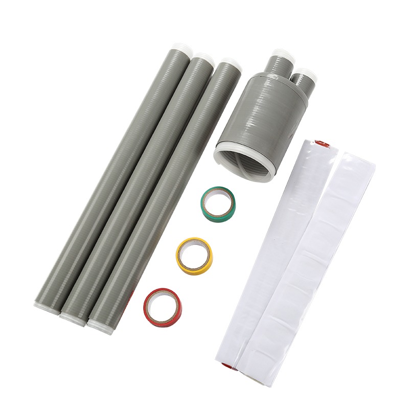
Moisture is the most common cause of an early joint failure and it is almost always introduced during installation. Cable ends that have stood in a duct for weeks take water under the sheath; assembled over a damp surface, that water is sealed in. Drying the cable, cleaning with the solvent supplied in the kit and assembling promptly are procedural controls, not product features.
Voids come from the same family. A cold-shrink sleeve is released from the center outward so air leaves at both ends; a sleeve pulled on from one end can trap a bubble that only shows up at the partial-discharge test. Filler tape, where the kit uses it, is applied under tension and in the direction the instructions give, because its job is to fill the space between cores rather than to wrap the joint.
The crimp is the third silent failure. A compression connector needs the matching die, the correct number of crimps along the barrel, and no rotation of the lug after the first crimp. A wrong die can leave a crimp that looks complete and still measures high resistance, so a resistance or millivolt-drop check on the first day's sample is worth more than an inspection at the end of the shift.
Joint or termination: the kit changes at the cable end
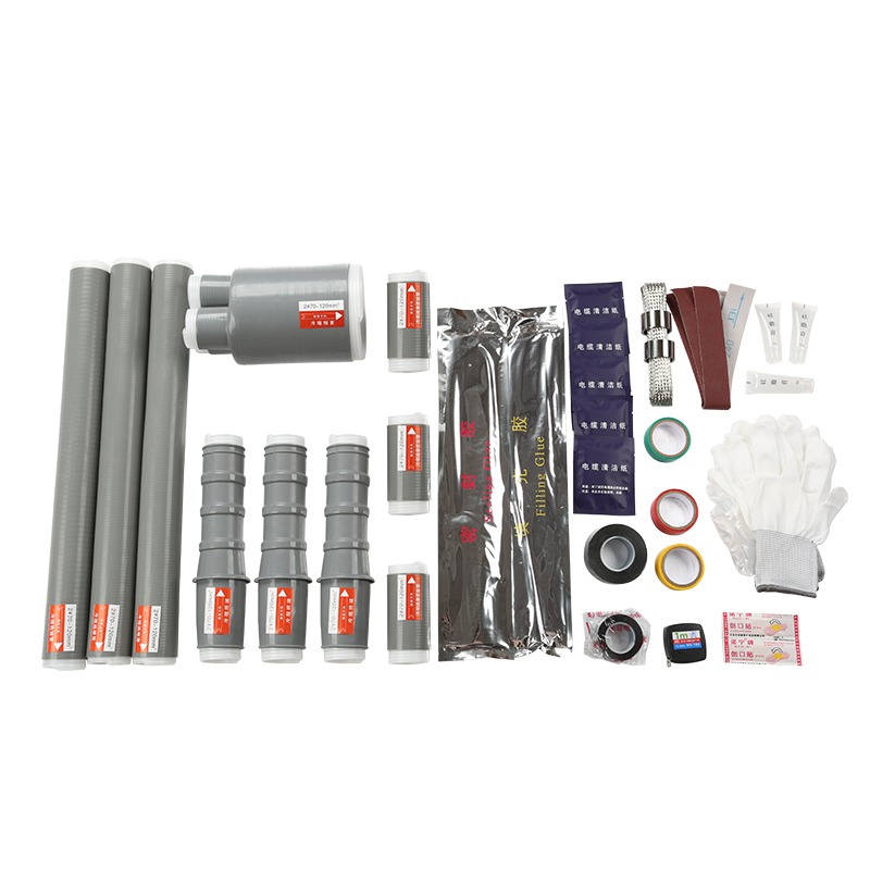
A joint connects two cable lengths and carries the screen through; a termination ends the cable and controls the field where the screen stops for good. The parts are not interchangeable, and the usual purchasing error is to order one type for both duties because the voltage class matches. A three-core termination carries a breakout that splits the cores and phase-marked sheds; an intermediate joint carries a joint body plus the filler and bonding parts the screen needs.
The difference is visible in the box, which is why the two pages are worth reading side by side before an inquiry goes out: the three-core cold-shrink termination kit and the three-core intermediate joint for 0.6/1 kV cable share the sleeve technology and almost nothing else. At medium voltage the same split applies, with an outdoor termination adding shed profile and creepage that an indoor joint does not need.
What to write into the cable joint kit RFQ
An inquiry that states the following can be quoted without a clarification round, and it gives the buyer a document to reject a delivery against. Write each line as a requirement.
- Voltage class and system earthing, for example 0.6/1 kV or 12/20 (24) kV, and whether the item is a joint or a termination.
- Cable construction for every cable the kit may serve: single-core or multicore, conductor material and cross-section, insulation type, and diameter over insulation and over screen.
- Screen and armour construction, stating whether armour continuity and bonding parts must be in the kit.
- Installation environment: indoor cable room, outdoor joint bay, duct or direct burial, and whether a heat source is permitted.
- Kit contents by name, so a missing ferrule is a short delivery rather than an argument: sleeves, stress control, connector, filler, bonding braid, cleaning materials, gloves.
- Documents: installation instructions in the project language, a kit content list, and type test evidence to IEC 61442 for the accessory family.
- Test regime after installation: insulation resistance, sheath test where applicable, and the withstand or partial-discharge test the utility requires.
- Packing: one kit per joint or per cable end, labelled with the cable size it suits, so kits are not mixed on site.
Where Nahu Group Fits
Nahu Group supplies cold-shrink cable accessories for 0.6/1 kV distribution cable and for medium-voltage cable up to 35 kV: terminations, intermediate joints and the branch-box hardware that goes with them, in three-core and single-core constructions, indoor and outdoor, as kits with the sleeves, stress control, connectors and tapes for the quoted size band. To configure a kit, send the cable specification rather than the cross-section alone: voltage class, conductor material and size, insulation diameter, screen and armour construction, indoor or outdoor, and the number of joints and terminations. A method statement or the utility's accessory specification helps too, because it states which tests the kit has to satisfy. The five-core cold-shrink termination page shows how a kit is broken down by size; if the question is what a kit should contain at all, the joint kit specification guide answers it. Cable ends that need a different assembly are covered in cold-shrink against heat-shrink terminations.
Frequently asked questions about cable joint kits
Is a cable joint kit the same as a termination kit?
No. A joint connects two cable lengths and carries the screen through; a termination ends the cable and controls the field where the screen stops. They share sleeve technology but not parts, and a joint body cannot substitute for an outdoor termination.
Which dimension decides the kit size?
The diameter over the insulation, and for screened cable the diameter over the screen. Conductor cross-section only indexes the catalogue. Measure the actual cable and quote the range, since two cables of the same cross-section can differ by several millimetres.
Can a joint be backfilled before testing?
Not where the test result is a hold point. If the joint fails a sheath or withstand test after backfill, the repair includes excavation. Keep the joint accessible until the test sheet is signed.
What test evidence should the supplier provide?
Type test reports for the accessory family to IEC 61442, covering AC withstand, impulse, partial discharge and thermal short-circuit tests, plus installation instructions and a kit content list. Ask for the report number and the cable range it covers.
Why do joints fail years after passing commissioning?
Usually a void or a moisture path left inside the joint, or stress control not seated against the screen edge. Both survive a short commissioning test and grow under load and thermal cycling, which is why the workmanship checks carry more weight than the final test.
Sources and Further Reading
- IEC 61442 — test methods for accessories for power cables rated 6 kV to 30 kV — sets the AC withstand, impulse, partial-discharge and thermal short-circuit tests a joint or termination must pass.
- IEC 60502-2 — power cables with extruded insulation and their accessories, 1 kV to 30 kV — defines the cable the accessory has to fit, including insulation and screen dimensions.
- Egyptian Electricity Holding Company — specification for cable joints, XLPE insulated cables 12/20 (24) kV — a utility specification showing joint type definitions, the applicable-standards table and screen and armour bonding clauses.
Published Nov 5, 2026 · Nahu Group (NAHU Electric Technology)