
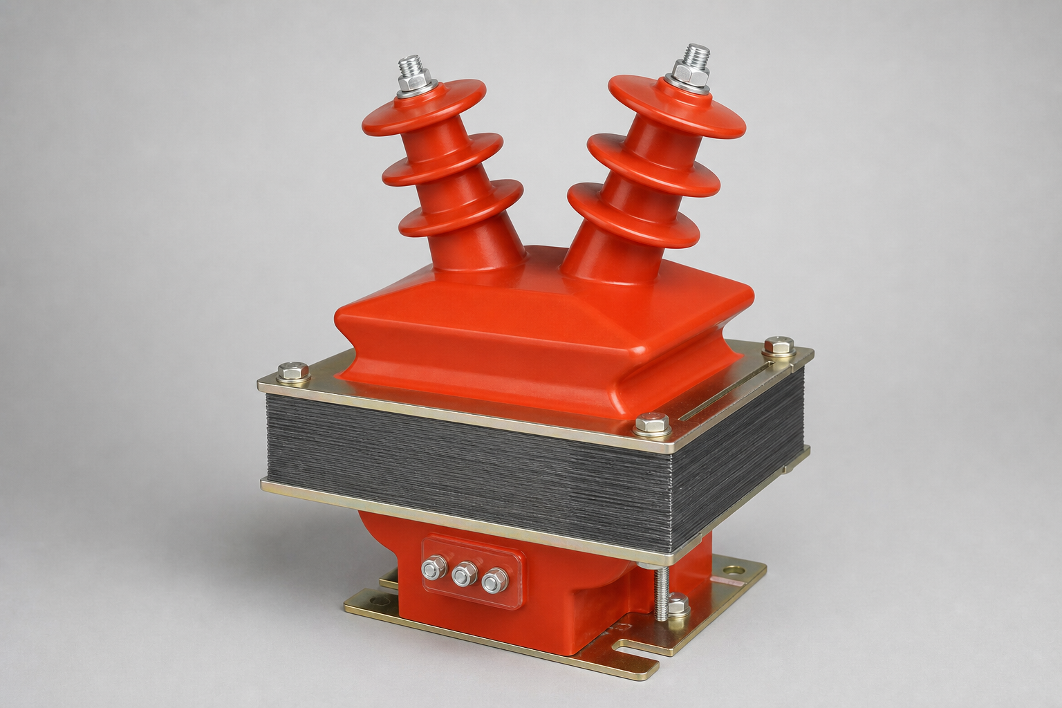
A voltage transformer scales high voltage proportionally down to 100 V, or a lower standard secondary voltage, for use by protection, metering and instrument equipment. At the same time it isolates that high voltage from the people working on the installation.
The mirror image of a CT
A voltage transformer also works by electromagnetic induction, but its electromagnetic arrangement is the opposite of a current transformer's. A CT primary is wound from heavy conductor with only one or a few turns, so its impedance is extremely low; connected in series with the circuit under test, the voltage drop across it is minimal. Its secondary has many turns, yet under normal conditions its EMF is only a few volts.
A high-impedance secondary
The voltage transformer secondary circuit is a high-impedance circuit, and the secondary current is set by that circuit impedance. As the secondary load impedance falls, secondary current rises, and the primary current automatically increases by a corresponding component to maintain the electromagnetic balance between primary and secondary. A voltage transformer is best understood as a special transformer, restricted in construction and in the way it is used — in short, a sensing element.
The 100 V secondary standard
Whatever the system voltage — 3.3 kV, 10 kV, 35 kV — the VT delivers the same standard secondary: 100 V phase-to-phase, or 100/√3 V phase-to-earth. That single convention is what makes meters, relays, transducers and test equipment interchangeable across manufacturers and across voltage classes. A ratio written as 10/0.1 kV means 10 kV on the primary gives 100 V on the secondary; on earthed systems the phase-to-earth winding is marked 10/√3 : 0.1/√3 kV. When you read a VT nameplate, the secondary standard is the anchor — everything else is the scaling and the accuracy.
Isolation and safety
The second job of the VT is galvanic isolation. The instrument and relay circuits are separated from the high-voltage network by the transformer's insulation, so the people working on the control panel touch only low-voltage equipment. One point of the secondary circuit is earthed to fix its potential, and the HV primary is fused so a failure is isolated quickly. The result: accurate measurement and protection, with the dangerous part of the installation physically and electrically out of reach.
Frequently asked questions
Why is the standard VT secondary voltage 100 V?
It is the international convention around which meters, relays and test equipment are designed. Standardising the secondary makes equipment interchangeable across system voltages.
What does a VT ratio of 10/0.1 kV mean?
10 kV of primary voltage produces 100 V at the secondary terminals — the standard scaling for a 10 kV network.
Do VTs need fuses?
Yes — a correctly rated HV fuse protects the primary against internal failure, and the secondary circuit should have LV protection so a secondary fault cannot overload the winding.
How does a VT isolate high voltage from the instruments?
Through its rated insulation between primary and secondary windings. The secondary side is a galvanically separate, low-voltage circuit — that is what keeps personnel safe.