
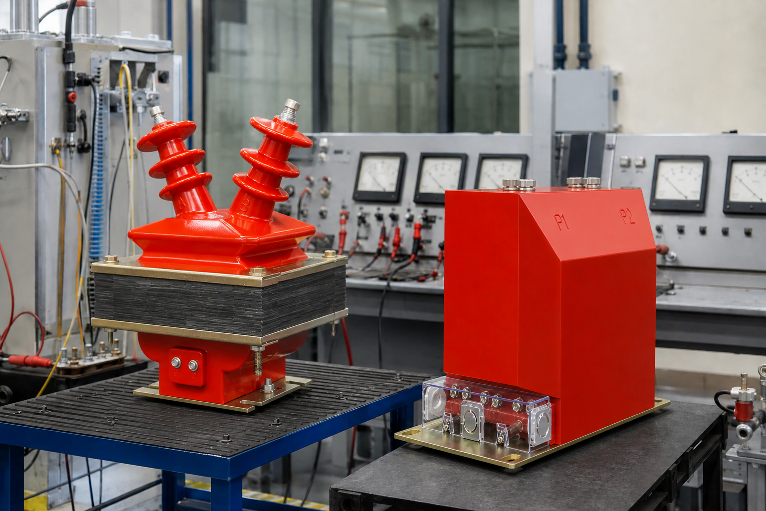
A current transformer (CT) and a voltage transformer (VT, also PT) both work on electromagnetic induction, and both exist to monitor an electrical circuit — the CT supplying the current signal to secondary instruments and protection, the VT supplying the voltage signal. Beyond that, they differ in almost every practical respect.
Construction
A CT primary is wound from heavy conductor, typically just one or a few turns, and is connected in series with the load whose current is being measured. A VT is a step-down transformer: its primary has many turns and is connected in parallel with the high-voltage network, while its secondary has few turns and connects to the voltage coil of a voltmeter or wattmeter.
Source behaviour
Relative to the secondary burden, a VT primary internal impedance is small enough to ignore, so a VT behaves as a voltage source. A CT primary internal impedance is very large, so a CT behaves as a current source of effectively infinite internal impedance.
Flux density
In normal service a VT operates with flux density close to saturation, and flux density falls during a fault. A CT operates at very low flux density normally, but during a short circuit the large primary fault current drives flux density up sharply, sometimes far beyond the saturation value.
What follows from that
Because of those opposite failure modes, a CT secondary must not be fitted with switches or fuses, whereas a VT secondary should have both. When commissioning newly installed VTs and CTs, or after replacing secondary cabling, always verify the correctness of the wiring and the polarity of the corresponding terminals.
Why CTs and VTs fail differently
The two transformers obey opposite safety rules because they behave like opposite sources. A current transformer is a current source: its secondary current is forced by the primary current, and if the secondary circuit is opened the flux path has nowhere to go — the voltage across the open terminals can rise to several kilovolts, arcing over and endangering personnel. A voltage transformer is a voltage source: its secondary impedance is very low, so a short circuit on the secondary side drives a heavy current that can burn out the winding within seconds. Remember the pair as "CT never open, VT never short".
This difference also explains the wiring. CT secondaries are always terminated into a meter, a relay or a shorting link, and only one point of the circuit is earthed. VT secondaries are fused or protected on the LV side, and one terminal is earthed to fix the potential of the whole secondary system.
Wiring CTs and VTs together for a complete metering installation
A high-voltage energy meter needs both quantities: active energy is the integral of voltage × current × time. The CT steps the line current down to 5 A or 1 A; the VT steps the line voltage down to 100 V or 100/√3 V; the meter multiplies the two and integrates. That is exactly what a combined high-voltage metering box does in one enclosure — factory-matched CTs and VTs, tested together, so the total error of the installation is known rather than guessed.
Frequently asked questions
Can a current transformer be used as a voltage transformer?
No. The core design, winding arrangement, ratio and connection are fundamentally different. Applying a VT as a CT — or the reverse — is dangerous and will not produce a usable signal.
Why must a CT secondary never be opened while energised?
An open secondary forces the core to carry the full primary ampere-turns, producing a high voltage across the open terminals — enough to arc over insulation and create a shock hazard.
Why must a VT secondary never be short-circuited?
A VT is designed for a high-impedance load. A short circuit removes the load impedance and lets the secondary current rise until the winding overheats and fails.
Do the errors of the CT and the VT add together in a metering installation?
Yes — the total installation error is the vector combination of the CT error, the VT error and the meter error. That is why combined metering boxes are matched and tested as one unit.