
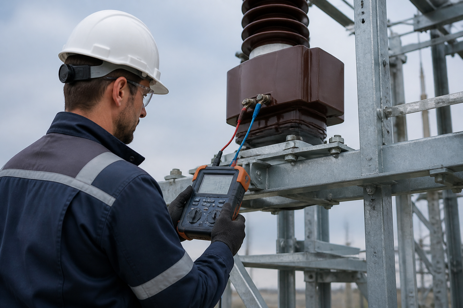
Most instrument transformer problems at site are not transformer problems at all — they are wiring, polarity and ratio mistakes made during installation. This checklist is the sequence our field engineers run before energising any metering or protection point.
Visual and mechanical inspection
Check the unit for shipping damage: cracked insulation, bent terminals, broken skirts. Confirm the nameplate ratio and class match the order, and that the serial number ties to the test certificate. Check earthing points, mounting bolts and that primary and secondary terminal markings are legible.
Insulation resistance before energisation
Use a 2.5 kV or 5 kV megohmmeter to measure primary-to-secondary, primary-to-earth and secondary-to-earth insulation. Compare against the manufacturer values — cast-resin units typically read hundreds of megohms to tens of gigohms when dry. A low reading usually means moisture ingress, not a failed unit.
Ratio and polarity verification
Inject a low voltage into the primary and compare the secondary output against the nameplate ratio. For CTs, a primary injection of 10–50 A through a calibrated clamp confirms the actual ratio and, with a polarity tester, that P1/S1 and P2/S2 markings are correct. On dual-ratio units, test both terminal combinations.
Secondary wiring continuity
Ring out every secondary conductor from the transformer terminal to the meter or relay, and confirm the earth is on the correct side — CT secondaries earth one terminal only, and VT secondary circuits earth at one point only. Verify phase rotation A–B–C reaches the meters in the right order and that no secondary is fused on a CT circuit.
Pre-energisation and energisation checks
With all secondary loads connected, energise and verify each meter and relay reads the expected values, disc rotation or LED pulses are steady, and phase-to-phase voltages agree with the nameplate ratio. Let the point run loaded for an hour and confirm readings stay stable before signing off the commissioning report.
When site testing is mandatory
On-site testing is mandatory for new installations before first energisation, after any repair or re-termination, after a suspected fault (lightning, through-fault, or a protection operation), and as part of the periodic verification programme. The tests protect three things: the accuracy of the revenue measurement, the reliability of the protection scheme, and the safety of the personnel who will work near the unit. A unit that passes its factory test certificate can still be wrong on site — damaged in transport, wrongly wired, or connected to the wrong burden.
Tools and a practical test sequence
A basic on-site kit: insulation resistance tester (megohmmeter), a portable CT analyzer or injection set for ratio and polarity, a multimeter for continuity and secondary voltage, and the manufacturer's datasheet for comparison. The practical order is: visual inspection of terminals, seals and earth connections; insulation resistance of each winding to earth and between windings; ratio check by primary injection; polarity verification against the markings; continuity and torque check of the entire secondary loop; then secondary voltage checks on the VT side with the unit energised at reduced or rated voltage. Record every value on the site test sheet — it becomes the baseline for all future comparisons.
Frequently asked questions
What is the acceptable insulation resistance for a CT or VT?
Typically above 1 GΩ when measured with the appropriate megohmmeter voltage (2.5 kV or 5 kV class), and never below the manufacturer's minimum. Compare with the factory certificate and trend over time.
How do you test the CT ratio on site?
Inject a known current into the primary (or use a portable CT analyzer) and measure the secondary current; the ratio must match the nameplate within the accuracy class limits.
What is a polarity test and why is it done?
It verifies that S1/S2 (or the VT terminals) correspond to P1/P2 as marked, so the metering and protection circuits see the correct phase relationship.
How do you verify the VT secondary wiring on site?
Measure the secondary voltages phase-to-phase and phase-to-earth with the unit energised, and confirm they match the ratio (for example 100 V or 100/√3 V on a 10/0.1 kV unit) and that the phase sequence is correct.