
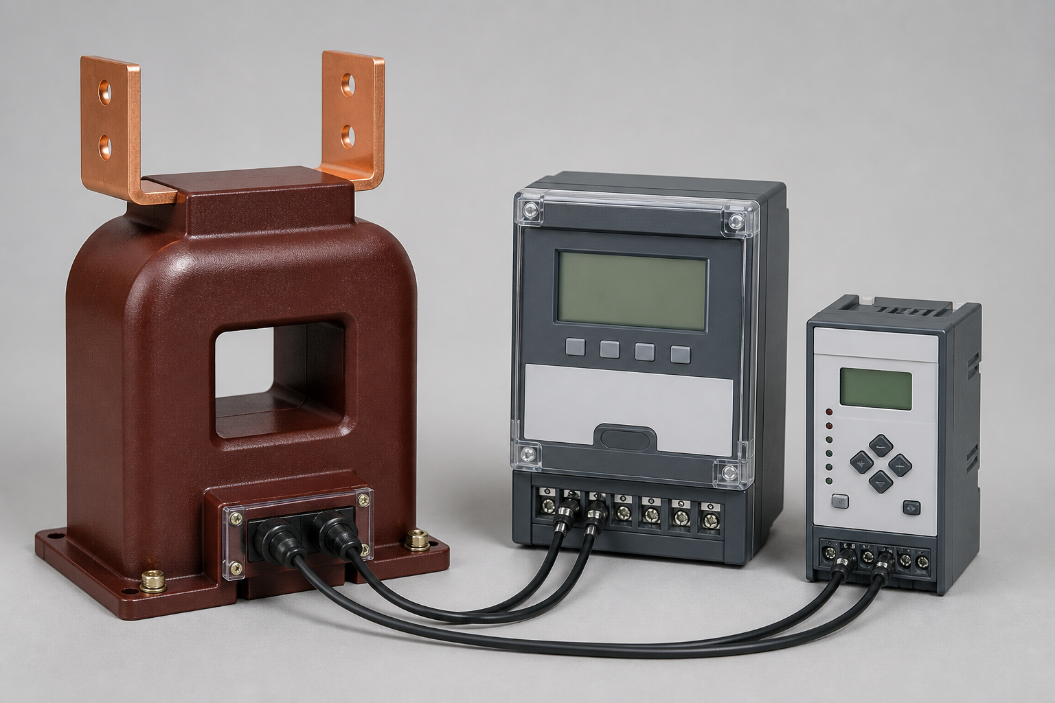
Every current transformer datasheet lists a rated output in VA — usually 5, 10, 15 or 20 VA for metering units. That number is the burden, and it is the single most common cause of inaccurate metering and unexplained relay misoperation when it is chosen wrongly.
What burden actually means
The burden is the total impedance of everything connected to the CT secondary: meters, relays, pilot wires and terminal connections. It is expressed in VA at the rated secondary current, usually 5 A. A 10 VA rated output at 5 A means the CT holds its accuracy class while feeding a secondary load of up to 10 VA.
Why burden limits accuracy
A current transformer is designed as a near-ideal current source, but its core cannot deliver unlimited secondary power. Beyond the rated burden the core begins to saturate, the secondary current waveform distorts, and the ratio error grows past the class limit. Below the rated burden the same unit usually performs better, which is why oversizing is safe and undersizing is not.
How to calculate the connected burden
Add the VA consumption of every instrument on the secondary circuit — meter current coils typically consume 0.5–2 VA each, relays 1–5 VA, and pilot wiring adds roughly VA = I² × R per phase. Compare the total with the CT rated output and keep at least 20–30% margin, so future meter replacements never push the circuit over its rating.
Sizing for protection relays
Protection cores add a second constraint: the accuracy limit factor. A 10P10 class with a given rated burden stays accurate up to 10 times rated current at that burden. If the relay burden is higher than the rated burden, the effective accuracy limit factor falls — check the curve or derate the factor before finalising the CT specification.
Practical rules of thumb
For a single electronic meter, 5 VA is normally enough. For a meter plus a relay on separate cores, pick 10 VA or 15 VA per core. For long secondary runs, compute the wire burden — it is often the largest component. When in doubt, send us the meter and relay models and the cable length; we will confirm the rated output on the datasheet.
Connected burden vs rated burden
The burden is the total load the CT secondary circuit presents to the transformer: the energy meter or relay (its VA consumption), plus the resistance of the secondary wiring and connections, plus the contact resistance of terminal blocks and shorting links. All of these add up and must stay at or below the rated burden printed on the CT nameplate — for example 10 VA or 30 VA. If the connected burden exceeds the rated burden, the transformer can no longer hold its accuracy class, and protection cores may saturate earlier during faults.
A useful rule: keep the connected burden at 50–80% of the rated burden when you can. That leaves margin for ageing contacts, extra instruments added later, and the difference between the theoretical and the real resistance of a long cable run.
How to reduce burden on long secondary runs
The wiring contribution to the burden is I²R, so the two levers are cable resistance and secondary current. Use a larger conductor cross-section on long runs, keep the run as short as possible, and — most effectively — specify a 1 A secondary instead of 5 A. Because the burden of the wiring is proportional to the square of the current, moving from 5 A to 1 A cuts the wiring burden by a factor of 25. That is why modern long-distance metering and protection schemes increasingly use 1 A CT secondaries.
Frequently asked questions
What happens if the burden exceeds the rated burden of the CT?
The ratio and phase errors increase beyond the class limits — billing becomes less accurate and protection cores may not pass the required fault current without saturating.
How do I calculate the connected burden of my installation?
Add the VA consumption of every connected instrument or relay to the wiring loss (I² × R for the full loop) and the contact resistance. Compare the total with the rated burden on the nameplate.
Why choose a 1 A secondary instead of 5 A?
For the same cable, a 1 A circuit carries 25 times less wiring burden than a 5 A circuit. It is the standard answer for long cable runs between the switchyard and the control room.
Does burden affect protection CTs the same way?
Yes. A 5P/10P class is only guaranteed up to its rated burden; overloading the secondary with extra burden makes the core saturate at a lower fault current and can delay or disable the protection operation.