
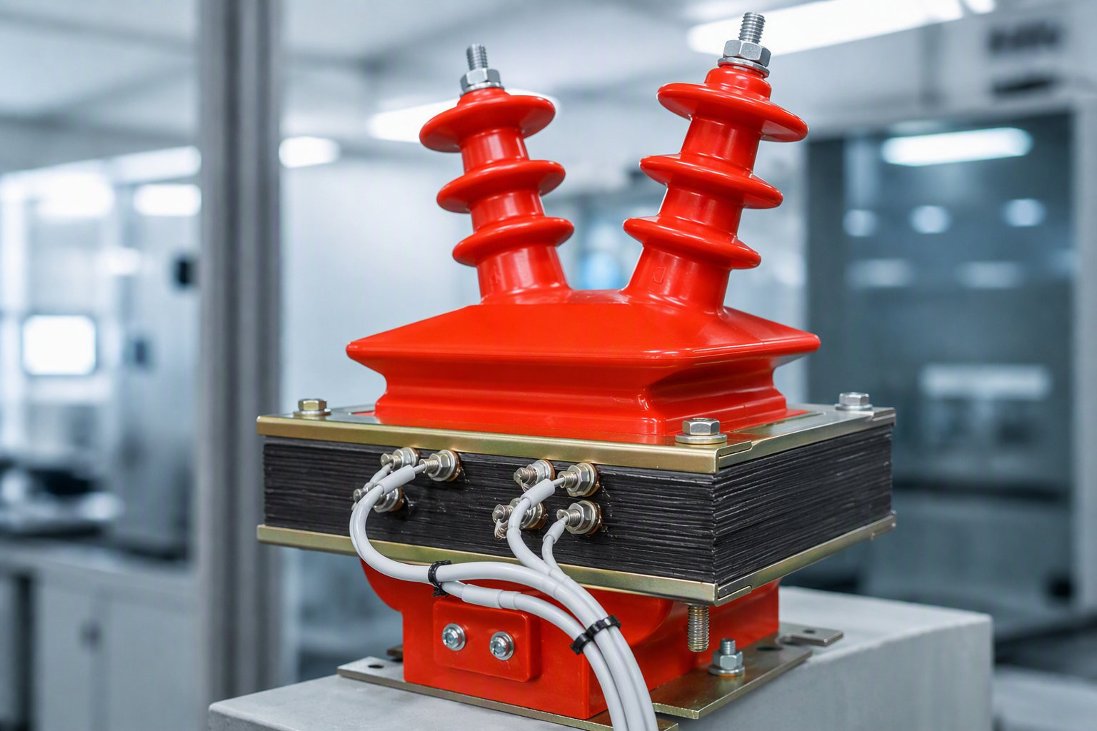
A voltage transformer works on the same principle as a power transformer, and its basic construction is also a core with primary and secondary windings. Its distinguishing characteristic is that its capacity is very small and fairly constant: in normal service it runs close to no-load.
Why the primary is fused and the secondary earthed
A voltage transformer's own impedance is very small, so if the secondary is short circuited the current rises sharply and burns out the winding. For that reason the primary is fitted with a fuse and the secondary is reliably earthed — the earth connection prevents a dangerous secondary-to-earth potential from appearing if the primary-to-secondary insulation fails, which would otherwise put both people and equipment at risk.
Single-phase, V-V and multi-tap variants
Measuring voltage transformers are generally built as single-phase, two-winding units. The primary voltage is the voltage being measured — typically a system line voltage. They can be used single-phase, or two units can be connected in a V-V arrangement to serve a three-phase application. Laboratory voltage transformers often have multiple primary taps so that different voltages can be measured.
The third winding
A voltage transformer intended for earth-fault protection carries an additional winding, making it a three-winding voltage transformer. In three-phase use, the third windings are connected in an open delta, and the two ends of that open delta connect to the voltage coil of the earth-fault protection relay.
In normal service the three system phase voltages are balanced, so the sum of the EMFs induced in the third windings is zero. If a single phase goes to earth, the neutral point is displaced and a zero-sequence voltage appears across the open-delta terminals, operating the relay and so protecting the system.
Core design
Because a zero-sequence voltage in the winding implies a corresponding zero-sequence flux in the core, this type of three-phase voltage transformer uses a side-yoke core at 10 kV and below, or is built as three separate single-phase units. Accuracy requirements for the third winding are not high, but it must have a degree of over-excitation capability: when primary voltage rises, core flux density rises by a corresponding factor without damage.
Voltage transformers are indispensable in power stations, substations and transmission and distribution systems generally. Precision voltage transformers are used in electrical test laboratories to extend measuring ranges for voltage, power and energy.
Voltage error and phase displacement
A VT's accuracy is expressed by two numbers: the ratio error in percent and the phase displacement in minutes. A 0.5-class VT, for example, holds its ratio error within ±0.5% and its phase error within ±20 minutes across the declared range. These limits matter because a phase error in the voltage signal rotates the current vector seen by the meter and the relays — an un-corrected phase error changes both the measured energy and the reach of distance protection. That is why metering VTs are specified by class, and why the class is only valid within the rated burden and voltage range printed on the plate.
Why the primary is fused and the secondary earthed
The VT primary is connected directly across the line, so a winding failure would otherwise become a phase-to-earth fault fed by the system. A correctly rated HV fuse isolates the failed unit quickly. On the secondary side, one terminal is earthed: this fixes the potential of the entire metering and protection circuit to earth, prevents the secondary system from floating at a dangerous voltage, and gives earth-fault detection a defined reference. The open-delta or broken-delta winding uses that reference: with the neutral earthed, the residual voltage across the open delta is near zero on a healthy system and rises to roughly 100/√3 V on a single-phase earth fault.
Frequently asked questions
Why does a voltage transformer run close to no-load?
Its only load is the instruments and relays connected to the secondary — a high-impedance, low-VA burden. The primary current stays tiny compared with a power transformer of the same rating.
What is an open-delta winding used for?
Earth-fault detection. The three phase voltages sum to zero on a healthy system, so the open-delta terminals are near zero; on an earth fault the residual voltage rises and drives the alarm or trip.
Which accuracy classes do VTs use?
Measuring windings are typically 0.2, 0.5 or 1.0; protection windings are 3P or 6P. The class limits both the ratio error and the phase displacement.
Why is the VT primary fused?
To disconnect the unit quickly if its internal winding fails, turning a potential phase-to-earth fault into a controlled, cleared event instead of a sustained one.